2-36
2
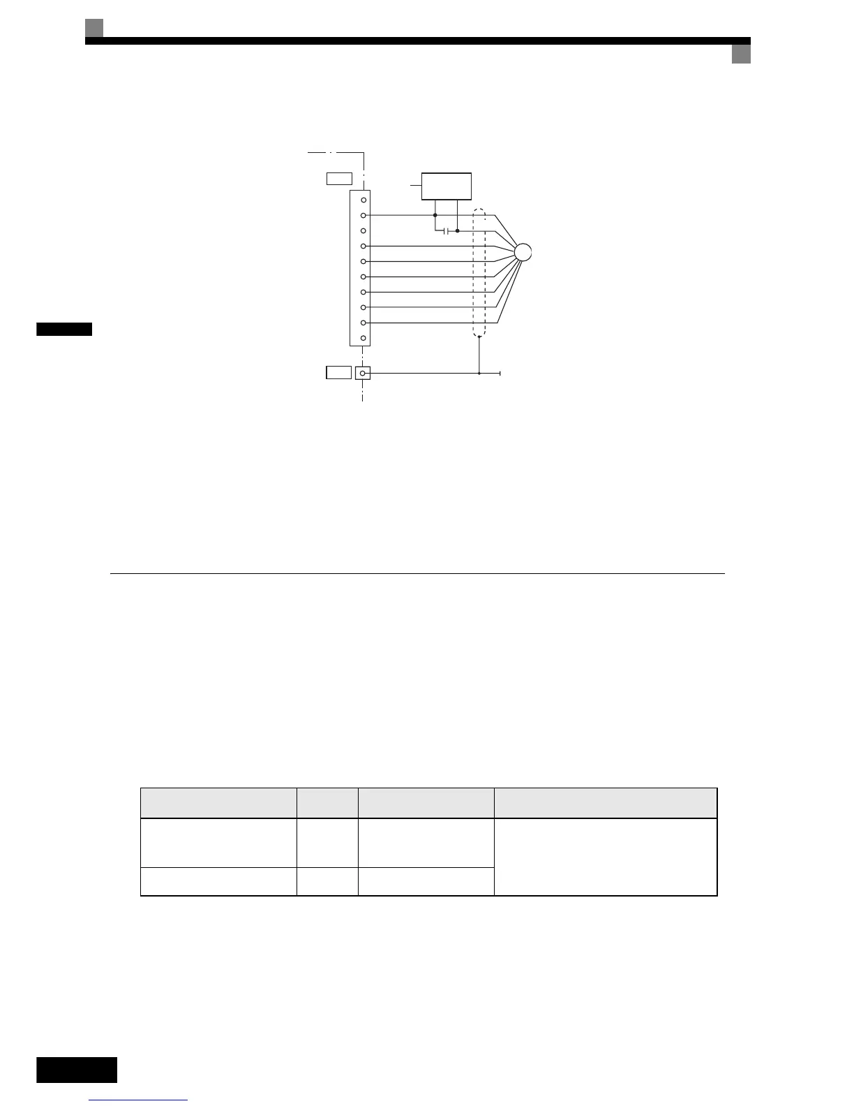
Fig 2.21 PG-X2 Wiring Using a 5 V External Power Supply
•
Shielded twisted-pair wires must be used for signal lines.
• Do not use the pulse generator's power supply for anything other than the pulse generator (encoder). Using
it for another purpose can cause malfunctions due to noise.
• The length of the pulse generator's wiring must not be more than 100 meters.
• The direction of rotation of the PG can be set in user parameter F1-05 (PG Rotation). The factory preset if
for motor forward rotation, A-phase advancement.
Wiring Terminal Blocks
Do not use more cables longer than 100 meters for wiring the PG (encoder) and keep them separate from
power lines.
Use shielded, twisted-pair wires for pulse inputs and pulse output monitor wires, and connect the shield to the
shield connection terminal.
Wire Sizes (Same for All Models)
Terminal wire sizes are shown in Table 2.15.
Straight Solderless Terminals
We recommend using straight solderless terminal on signal lines to simplify wiring and improve reliability.
Refer to Table 2.8 for specifications.
Table 2.15 Wire Sizes
Terminal
Terminal
Screws
Wire Thickness (mm
2
)
Wire Type
Pulse generator power supply
Pulse input terminal
Pulse monitor output terminal
-
Stranded wire: 0.5 to 1.25
Single wire: 0.5 to 1.25
• Shielded, twisted-pair wire
• Shielded, polyethylene-covered, vinyl
sheath cable
(KPEV-S by Hitachi Electric Wire or
equivalent)
Shield connection terminal M3.5 0.5 to 2
TA1
IP12
IG
IP5
A (+)
A (-)
B (+)
B (-)
Z (+)
Z (-)
IG
TA3
PG-X2
1
2
3
4
5
6
7
8
9
10
AC
PG
+
+
+
-
-
0 V
Capacitor for
momentary
power loss
0V +12V
PG power
supply
+12 V
+
-