2-37
2
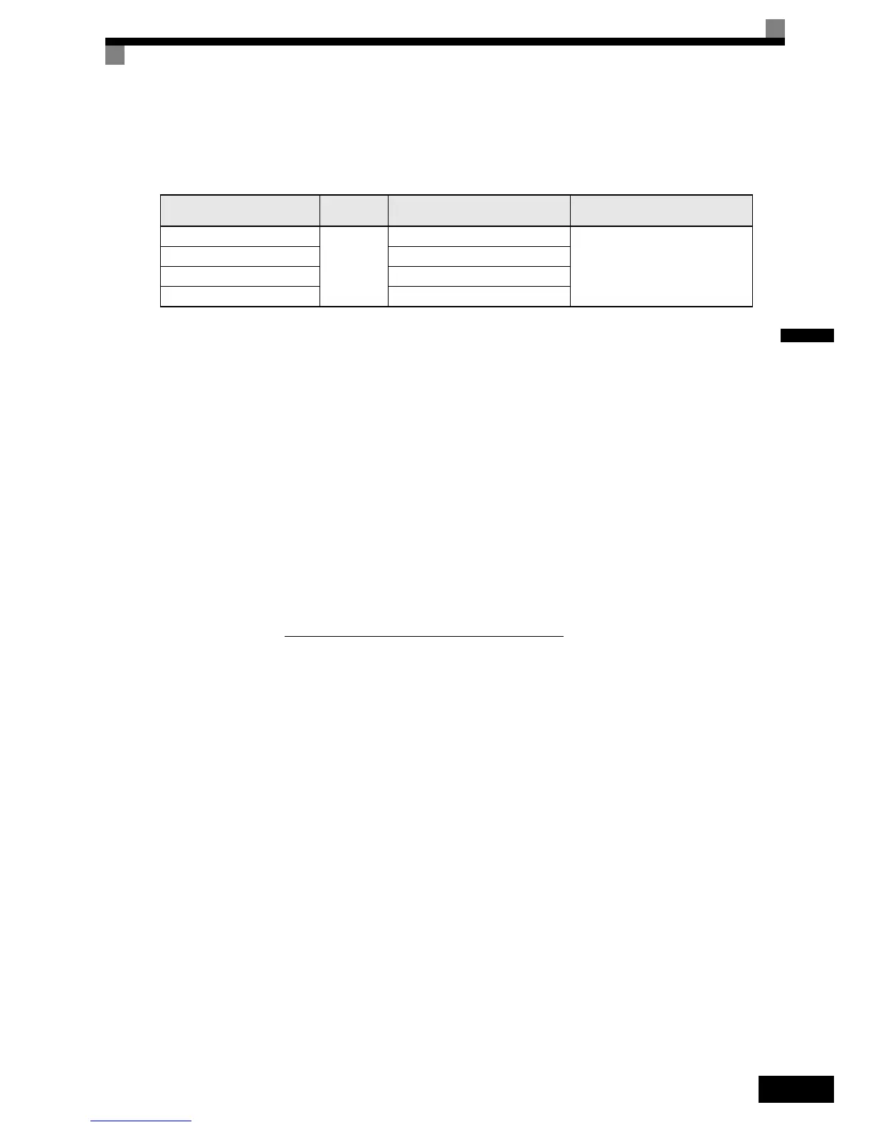
Cable Lug Connector Sizes and Tightening Torque
The lug sizes and tightening torques for various wire sizes are shown in Table 2.16.
Precautions
The wiring method is the same as the one used for straight solderless terminals. Refer to page 2-36. Observe
the following precautions when wiring.
• Separate the control signal lines for the PG Speed Control Card from main power lines and other control
circuits.
• The shield must be connected to prevent operational faults caused by noise. Also, do not use any lines that
are more than 100 m long.
• Connect the shield (green grounding cable of the option card) to the shield terminal (E).
• Do not solder the ends of wires. Doing so may cause contact faults.
• When not using straight solderless terminals, strip the wires to a length of approximately 5.5 mm
• A separate power supply is required if the PG power supply consumption is higher than 200 mA. (If
momentary power loss must be handled, use a backup capacitor or other method.)
• Make sure not to exceed the PG cards maximum input frequency. The output frequency of the pulse gener-
ator can be calculated using the following formula.
Table 2.16 Cable Lugs and Tightening Torque
Wire Thickness [mm
2
]
Terminal
Screws
Crimp Terminal Size Tightening Torque (N • m)
0.5
M3.5
1.25 - 3.5
0.8
0.75 1.25 - 3.5
1.25 1.25 - 3.5
2 2 - 3.5
f
PG
(Hz) =
Motor speed at maximum output frequency (min
–1
)
60
x PG rating (p/rev)

 Loading...


