1-6
1
Component Names
Inverters of 18.5 kW or Less
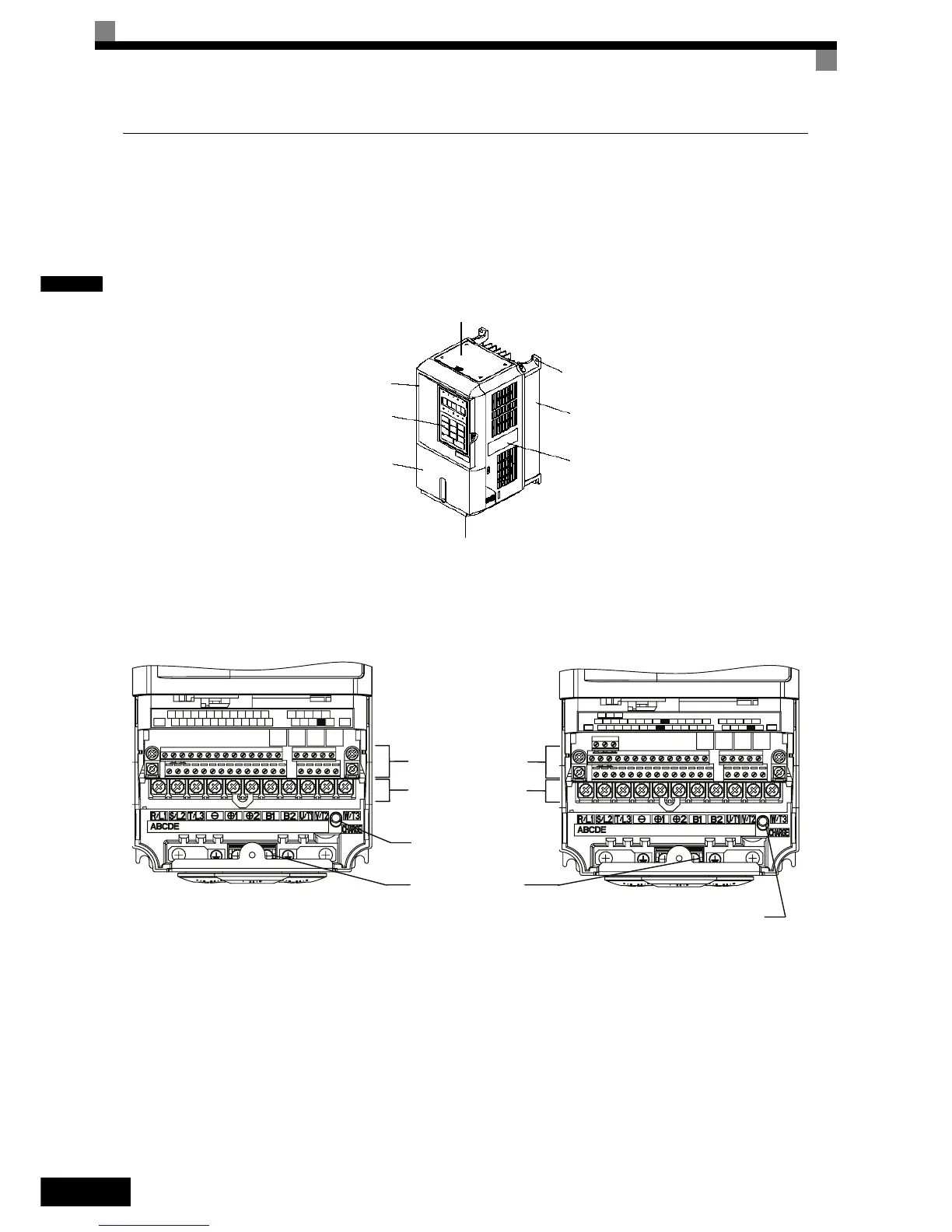
The external appearance and component names of the Inverter are shown in Fig 1.4. The Inverter with the ter-
minal cover removed is shown in Fig 1.5.
Fig 1.4 Inverter Appearance (18.5 kW or Less)
Fig 1.5 Terminal Arrangement of Standard and Safety Inverter (18.5 kW or Less)
Top protective cover (Part of Enclosed Wall-
mounted Type (IEC IP20, NEMA Type 1)
Front cover
Digital Operator
Terminal cover
Mounting
Nameplate
Diecast case
Bottom protective cover
$&
6
9 0
6 6
63
6 0
9
6
6& $
0
61 0$
(*
(*
0&0%
6 0
0$
06
$& $0
553$&
,*)0
03
6
5
6
E(G) S1 S2 S3 S4 S5 S6 S7 FM AC AM IG S+ S-
SN SC SP A1 A2 V+ AC V- MP AC RP R+ R-
M3 M4 M1 M2
M5 M6 MA MB MC
E( G)
BB BB1 SC
Control Circuit Terminals
Main Circuit Terminals
Charge Indicator
Ground Terminals
Charge Indicator
Standard Inverter
Safety Inverter

 Loading...


