9-4
9
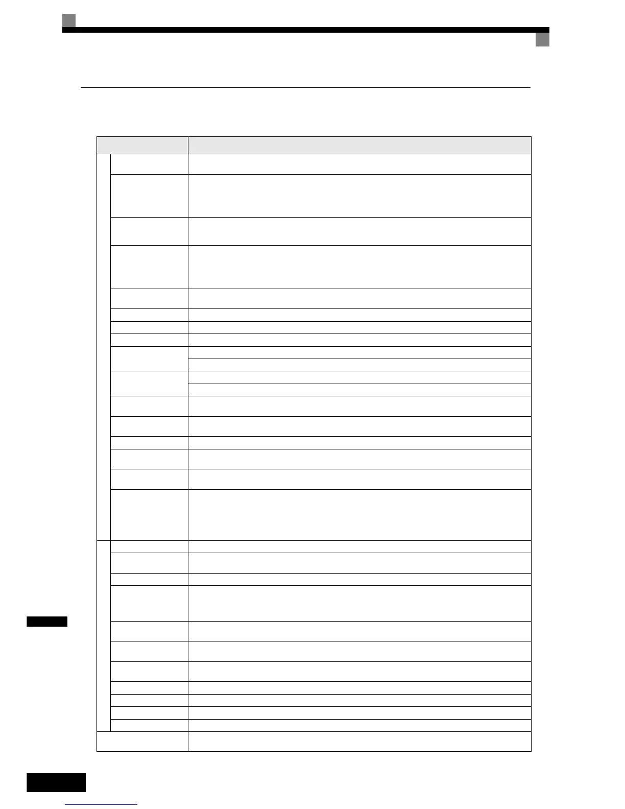
Common Specifications
The following specifications apply to both 200 V and 400 V class Inverters.
Model Number
CIMR-F7Z
Specification
Control method
Sine wave PWM
Closed Loop Vector control, Open Loop Vector control, V/f control, V/f with PG control
Torque characteristics
Heavy Duty (low carrier, constant torque applications): 2 kHz carrier frequency, 150% overload for 1 minute,
higher carrier frequency possible with current derating.
Normal Duty 1 (high carrier, variable torque applications): maximum carrier frequency, depending on inverter capacity,
120% overload for 1 minute.
Normal Duty 2 (variable torque applications): carrier frequency reduced, continuous overload capability increased
Speed control range
1:40 (V/f control)
1:100 (Open Loop Vector control)
1:1000 (Closed Loop Vector control)
Speed control accuracy
± 3% (V/f control)
± 0.03% (V/f control with PG)
± 0.2% (Open Loop Vector control)
± 0.02% (Closed Loop Vector control)
(25°C ± 10°C)
Speed control response
5 Hz (control without PG)
30 Hz (control with PG)
Torque limits Provided (4 quadrant steps can be changed by parameter settings.) (Vector control)
Torque accuracy ± 5%
Frequency range 0.01 to 150 Hz (Heavy Duty), 0.01 to 400 Hz (Normal Duty 1 or 2)
Frequency accuracy (tem-
perature characteristics)
Digital references: ± 0.01% (-10°C to +40°C)
Analog references: ± 0.1% (25°C ±10°C)
Frequency setting resolu-
tion
Digital references: 0.01 Hz
Analog references: 0.025/50 Hz (11 bits plus sign)
Output frequency resolu-
tion
0.01 Hz
Overload capacity and
maximum current
Heavy Duty (low carrier, constant torque applications): 150% of rated output current for 1 minute
Normal Duty 1 or 2 (high/reduced carrier, variable torque applications): 120% of rated output current for 1 minute
Frequency setting signal 0 to +10V, –10 to +10 V, 4 to 20 mA, pulse train
Acceleration/Decelera-
tion time
0.01 to 6000.0 s (4 selectable combinations of independent acceleration and deceleration time settings)
Braking torque
Approximately 20% (Approximately 125% with Braking Resistor option,
braking transistor built into Inverters of 18.5 kW or less)
Main control functions
Restarting after momentary power loss, speed search, overtorque/undertorque detection, torque limits, 17-speed control (max-
imum), 4 acceleration and deceleration times, S-curve acceleration/deceleration, 3-wire control, auto-tuning (rotational or sta-
tionary), dwell function, cooling fan ON/OFF control, slip compensation, torque compensation, auto-restart after fault, jump
frequencies, upper and lower limits for frequency references, DC braking for starting and stopping, high-slip braking,
advanced PID control, energy-saving control, MEMOBUS communications (RS-485/422, 19.2 kbps maximum), 2 motor
parameter sets, fault reset and parameter copy function.
Motor protection Protection by electronic thermal overload relay.
Instantaneous overcurrent
protection
Stops at approx. 200% of rated output current.
Fuse blown protection Stops for fuse blown.
Overload protection
Heavy Duty (low carrier, constant torque applications): 150% of rated output current for 1 minute
Normal Duty 1 (high carrier, variable torque applications): 120% of rated output current for 1 minute
Normal Duty 2 (high carrier, variable torque applications): 120% of rated output current for 1 minute,
increased continuous output current.
Overvoltage protection
200 Class Inverter: Stops when main-circuit DC voltage is above 410 V.
400 Class Inverter: Stops when main-circuit DC voltage is above 820 V.
Undervoltage protection
200 Class Inverter: Stops when main-circuit DC voltage is below 190 V.
400 Class Inverter: Stops when main-circuit DC voltage is below 380 V.
Momentary power loss
ride through
By selecting the momentary power loss method, operation can be continued if power is restored within 2 s.
Cooling fin overheating Protection by thermistor.
Stall prevention Stall prevention during acceleration, deceleration and running independently.
Grounding protection Protection by electronic circuits.
Charge indicator Glows when the main circuit DC voltage is approx. 10 VDC or more.
Protective structure
Enclosed wall-mounted type (NEMA 1): 18.5 kW or less (same for 200 V and 400 V class Inverters)
Open chassis type (IP00): 22 kW or more (same for 200 V and 400 V class Inverters)

 Loading...


