2-30
2
Installing and Wiring Option Cards
Option Card Models and Specifications
Up to two Option Cards can be mounted in the Inverter. You can mount one card into each of the two places on
the controller card (A, and C) like shown in Fig 2.16.
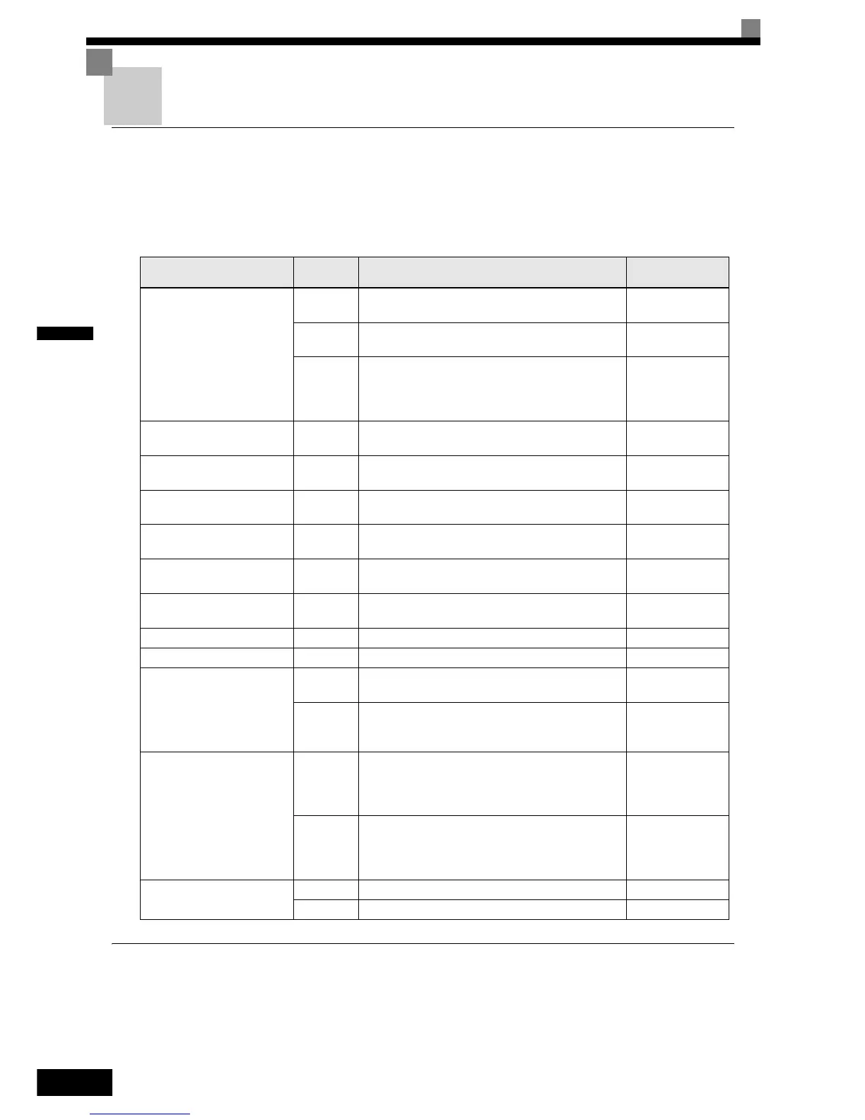
Table 2.12 lists the type of Option Cards and their specifications.
Installation
Before mounting an Option Card, remove the terminal cover and be sure that the charge indicator inside the
Inverter does not glow anymore. After that remove the Digital Operator and front cover and then mount the
Option Card.
Table 2.12 Option Cards
Card Model Specifications
Mounting
Location
PG Speed Control Cards
PG-B2
Two phase (phase A and B), +12V inputs, max.
response frequency: 50 kHz
A
PG-X2
Three phase (phase A, B, Z), line driver inputs
(RS422), max. response frequency: 300 kHz
A
PG-Z2
Dual encoder PG feedback card (two times phase A,
B, Z), selectable line driver (RS422) or open collector
inputs, max. response frequency 30 kHz (open collec-
tor) and 300 kHz (line driver)
A
DeviceNet
communications card
SI-N1/
PDRT2
Option card for DeviceNet fieldbus C
Profibus-DP
communications card
SI-P1 Option card for Profibus-DP fieldbus C
InterBus-S
communications card
SI-R1 Option card for InterBus-S fieldbus C
CANOpen
communications card
SI-S1 Option card for CANOpen fieldbus C
LonWorks
communication card
SI-J Option card for LonWorks fieldbus C
Mechatrolink II
communication card
SI-T1 Option card for Mechatrolink II fieldbus C
Modbus TCP/IP CM090 Option card for Modbus TCP/IP fieldbus C
Ethernet IP CM092 Option card for Ethernet IP fieldbus C
PLC option cards
3G3RV-
P10ST8-E
PLC option card C
3G3RV-
P10ST8-
DRT-E
PLC option card with DeviceNet communications
port (Slave)
C
Analog Input Cards
AI-14U
2 channel high resolution analog input card
Channel 1: 0 to 10 V (20 kΩ)
Channel 2: 4 to 20 mA (250 Ω)
Resolution: 14 Bit
C
AI-14B
3 Channel high resolution analog input card
Signal level: -10 to +10 V (20 kΩ)
4 to 20 mA (250 Ω)
Resolution: 13 Bit + sign
C
Digital Input Cards
DI-08 8 bit digital speed reference input card C
DI-16H2 16 bit digital speed reference input card C

 Loading...


