6-66
6
Selecting the Cooling Fan Control
Using parameter L8-10 two modes can be selected:
0: The fan is ON only when the inverter output is ON, i.e. a voltage is output. This is the factory setting.
1: The fan is ON whenever the inverter power supply is switched ON.
If L8-10 is set to 0, the turn OFF delay time for the fan can be set in parameter L8-11. After a stop command
the inverter waits for this time before switching OFF the cooling fan. The factory setting is 60 sec.
Setting the Ambient Temperature
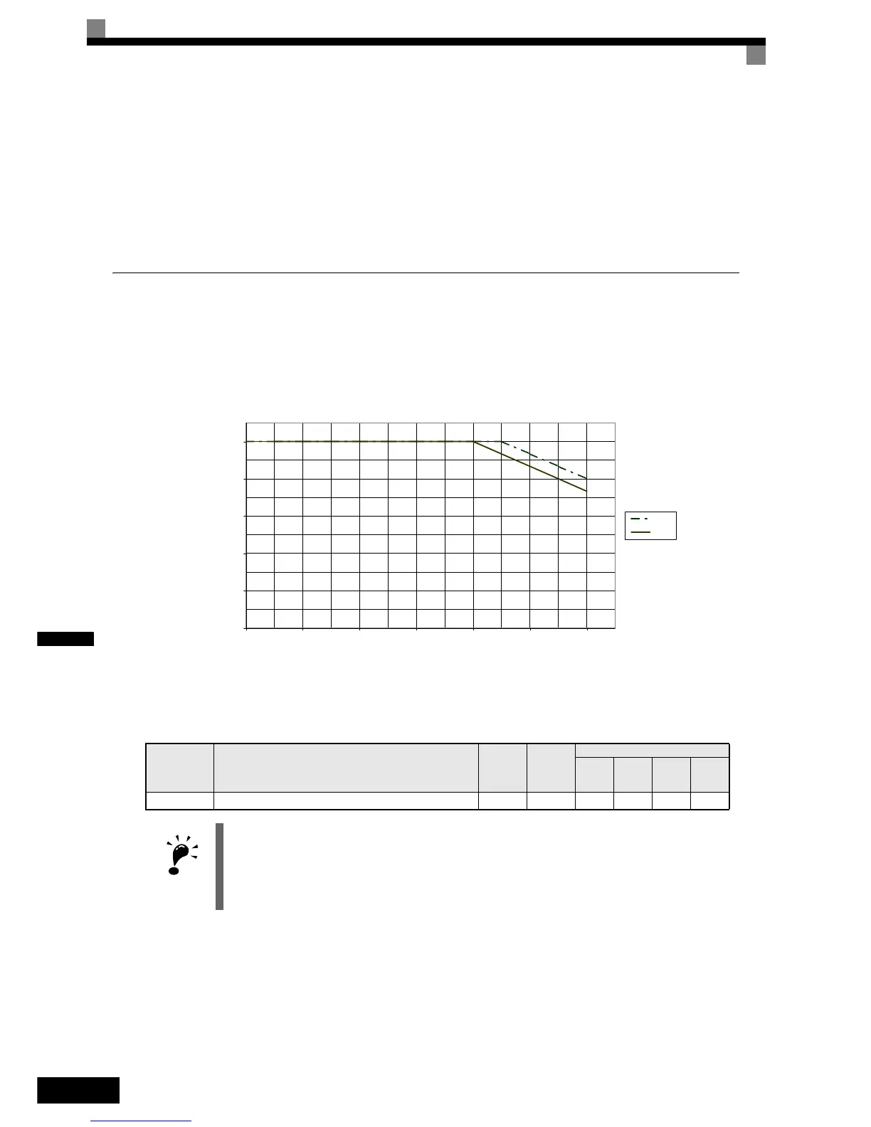
At high ambient temperatures the output current has to be derated. The derating depends on the ambient tem-
perature and the protective structure of the inverter. The ambient temperature derating curve is shown in Fig
6.65. To ensure a safe inverter protection at high ambient temperatures, always set parameter L8-12 to the
actual ambient temperature. The inverter overload capability will be 120% / 150% (depending on C6-01) of
the derated current for 1 minute.
Fig 6.65 Ambient Temperature Derating Curve
Related Parameters
Parameter
No.
Name
Factory
Setting
Change
during
Opera-
tion
Control Methods
V/f
V/f with
PG
Open
Loop
Vector
Closed
Loop
Vector
L8-12 Ambient temperature 45 °C No A A A A
IMPORTANT
Since the inverter has no IP00/ NEMA 1 (IP20) detection, with NEMA 1 (IP20) units the ambient tem-
perature value in L8-12 has to be set 5° higher than the actual ambient temperature.
0
20
40
60
80
100
0 102030405060
Temperature (°C)
Output Current in % of the
Rated Current
IP00
IP20

 Loading...


