2-35
2
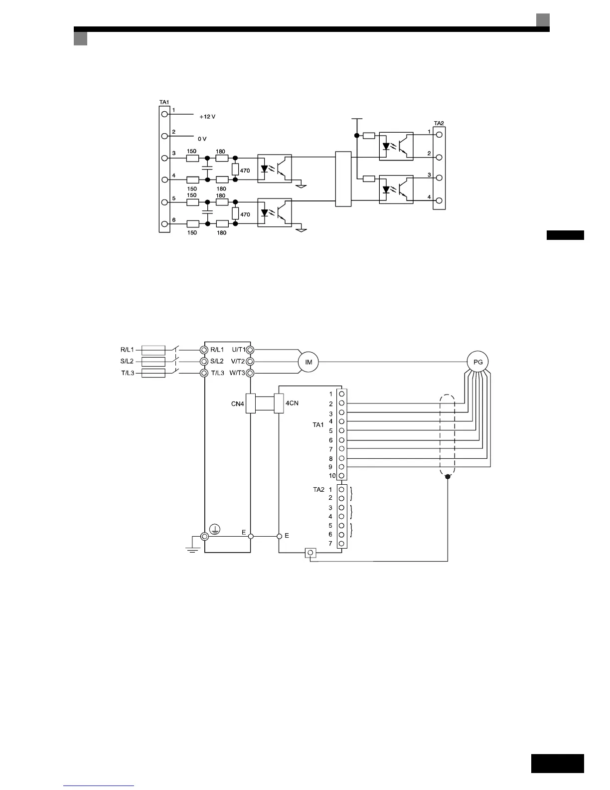
Fig 2.19 I/O Circuit Configuration of the PG-B2
Wiring the PG-X2
The following illustrations show wiring examples for the PG-X2 using the option cards power supply or an
external power source for supplying the PG.
Fig 2.20 PG-X2 Wiring Using the Option Cards Power Supply
PG power
supply
+12 V
Pulse input
phase A
Pulse input
phase B
A-phase
pulses
B-phase
pulses
Division rate
circuit
Pulse monitor
output phase B
Pulse monitor
output phase A
Inverter
+5 V
A-phase pulse input (+)
Pulse input phase A (–)
Pulse input phase B (+)
Pulse input phase B (–)
Pulse monitor output phase A
Pulse monitor output phase B
Pulse monitor output phase Z
0 V
PG-X2
Three-phase 200/400VAC
Pulse input phase Z (+)
Pulse input phase Z (–)
+12 V

 Loading...


