2-25
2
The functions of DIP switch S1 and jumper CN15 are shown in the following table.
Sinking/Sourcing Mode
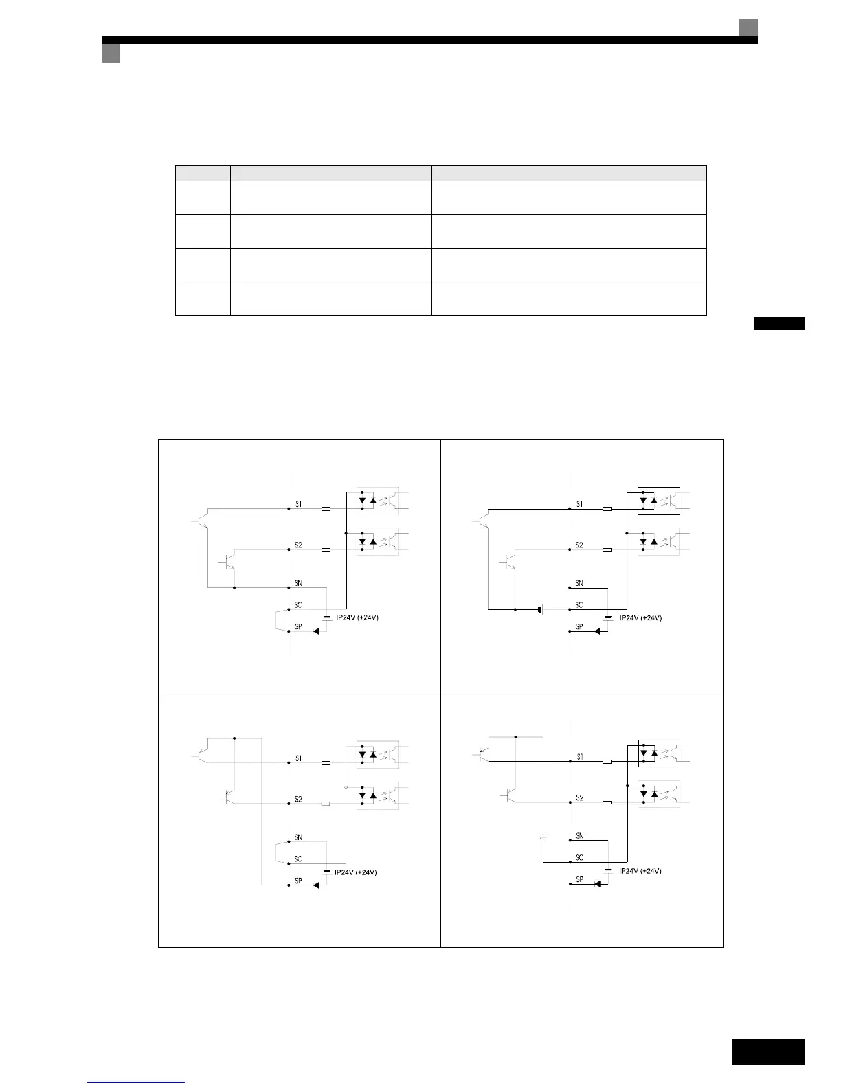
The input terminal logic can be switched between sinking mode (0-V common) and sourcing mode (+24V
common) by using the terminals SN, SC, and SP. An external power supply is also supported, providing more
freedom in signal input methods.
Table 2.10 DIP Switch S1 and Jumper CN15 Settings
Name Function Setting
S1-1
RS-485 and RS-422 terminating resis-
tance
OFF: No terminating resistance
ON: Terminating resistance of 110 Ω
S1-2 Input method for analog input A2
V: 0 to 10 V (internal resistance: 20 kΩ)
I: 4 to 20 mA (internal resistance: 250 Ω)
CN15-
CH1
Multifunction analog output FM voltage/
current switch
I: Current output
V: Voltage output
CN15-
CH2
Multifunction analog output AM voltage/
current switch
I: Current output
V: Voltage output
Table 2.11 Sinking/Sourcing Mode and Input Signals
Internal Power Supply – Sinking Mode
External Power Supply – Sinking Mode
External +24V
Internal Power Supply – Sourcing Mode
External Power Supply – Sourcing Mode
External +24V

 Loading...


