6-123
6
The direction of the torque output from the motor will be determined by the sign of the analog signal input or
a digital input command. It does not depend on the direction of the run command. The direction of torque will
be as follows:
• Positive analog reference: Torque reference for forward motor rotation (counterclockwise as viewed from
the motor output axis).
• Negative analog reference: Torque reference for reverse motor rotation (clockwise as viewed from the
motor output axis).
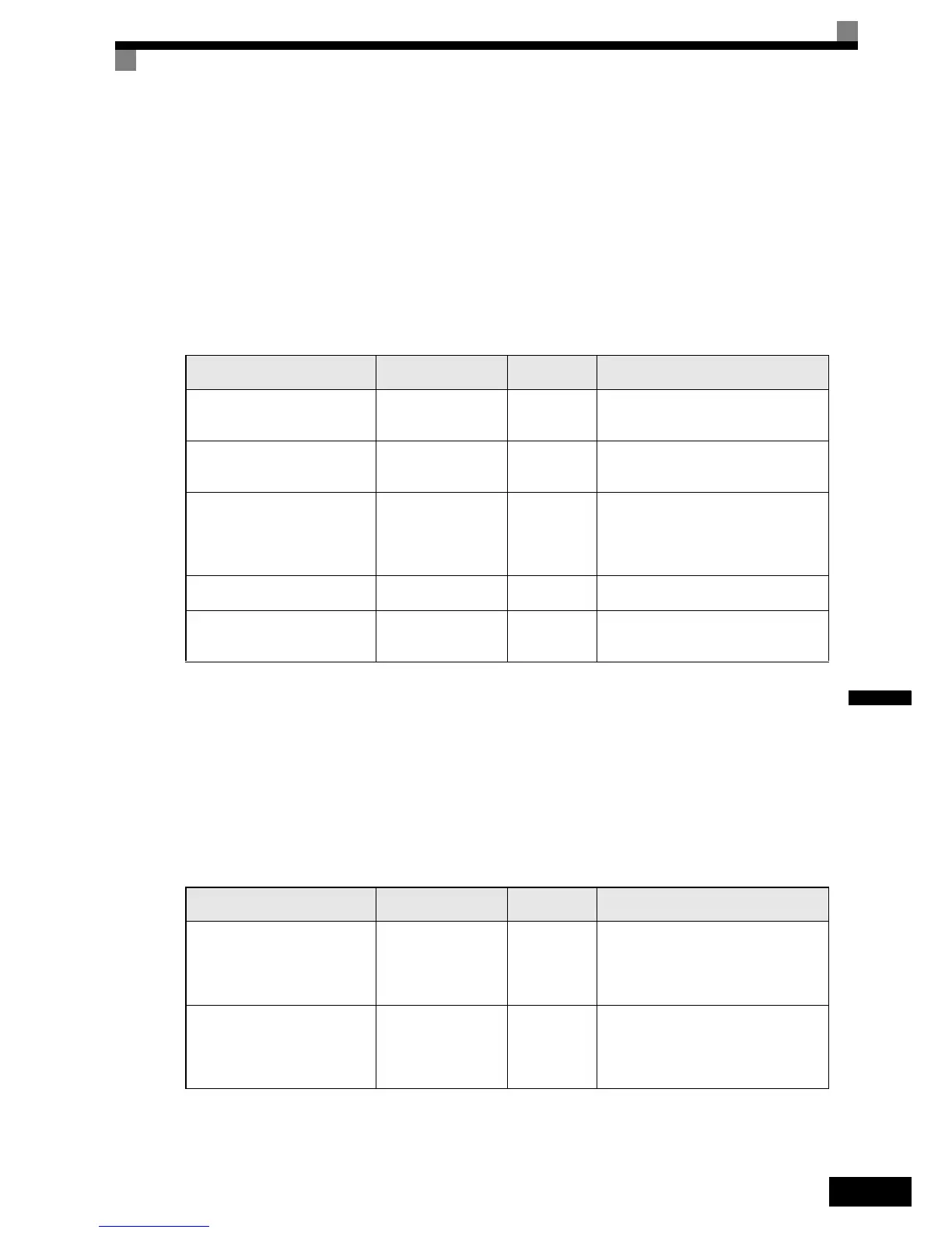
Inputting the Speed Limit
The inputs methods for a speed limit are listed in the following table.
The direction in which speed is controlled is determined by the sign of the speed limit signal and the direction
of the run command.
• Positive voltage applied: The speed in the forward direction will be limited for forward operation.
• Negative voltage applied: The speed in the reverse direction will be limited for reverse operation.
If the direction of the motor rotation and the speed limit direction are not the same, the speed will be limited
to 0.
Inputting the Torque Compensation
The input methods for a torque compenation listed in the following table.
Speed Limit Input Method
Location of Refer-
ence
Parameter
Settings
Remarks
Voltage input (0 to +10 V) Analog input A1
b1-01 = 1
d5-01 = 1
H3-01 = 0
Use this setting if the speed limit has
always to be positive.
Voltage input (-10 to +10 V) Analog input A1
b1-01 = 1
d5-01 = 1
H3-01 = 1
Use this setting when a speed limit for
both directions has to be applied.
Current input (4 to 20 mA) Analog input A2
b1-01 = 1
d5-01 = 1
H3-08 = 2
H3-09 = 13
H3-13 = 1
Terminal A1 becomes the torque reference
value (only voltage signal!)
Turn ON (I side) pin 2 of DIP switch S1
on the terminal board.
Parameter setting Set in d5-04
d5-01 = 1
d5-03 = 2
-
Option Card (AI-14B)
(0 to ±10 V)
Channel 1
b1-01 = 1
d5-01 = 1
F2-01 = 0
Channel 1 of the AI-14B card replaces
analog input A1
Torque Compensation Input
Method
Location of Refer-
ence
Parameter
Settings
Remarks
Voltage input (0 to +10 V) Analog input A1
b1-01 = 1
d5-01 = 2
d5-03 = 2
H3-01 = 0
H3-09 = 13
Use this setting if the torque if the torque
compensation has always to be positive.
The speed limit is then input in parameter
d5-04, torque reference at terminal A2.
Voltage input (-10 to +10 V) Analog input A1
b1-01 = 1
d5-01 = 2
d5-03 = 2
H3-01 = 1
H3-09 = 13
Use this setting when a speed limit for
both directions has to be applied.
The speed limit is then input in parameter
d5-04, torque reference at terminal A2.

 Loading...


