6-28
6
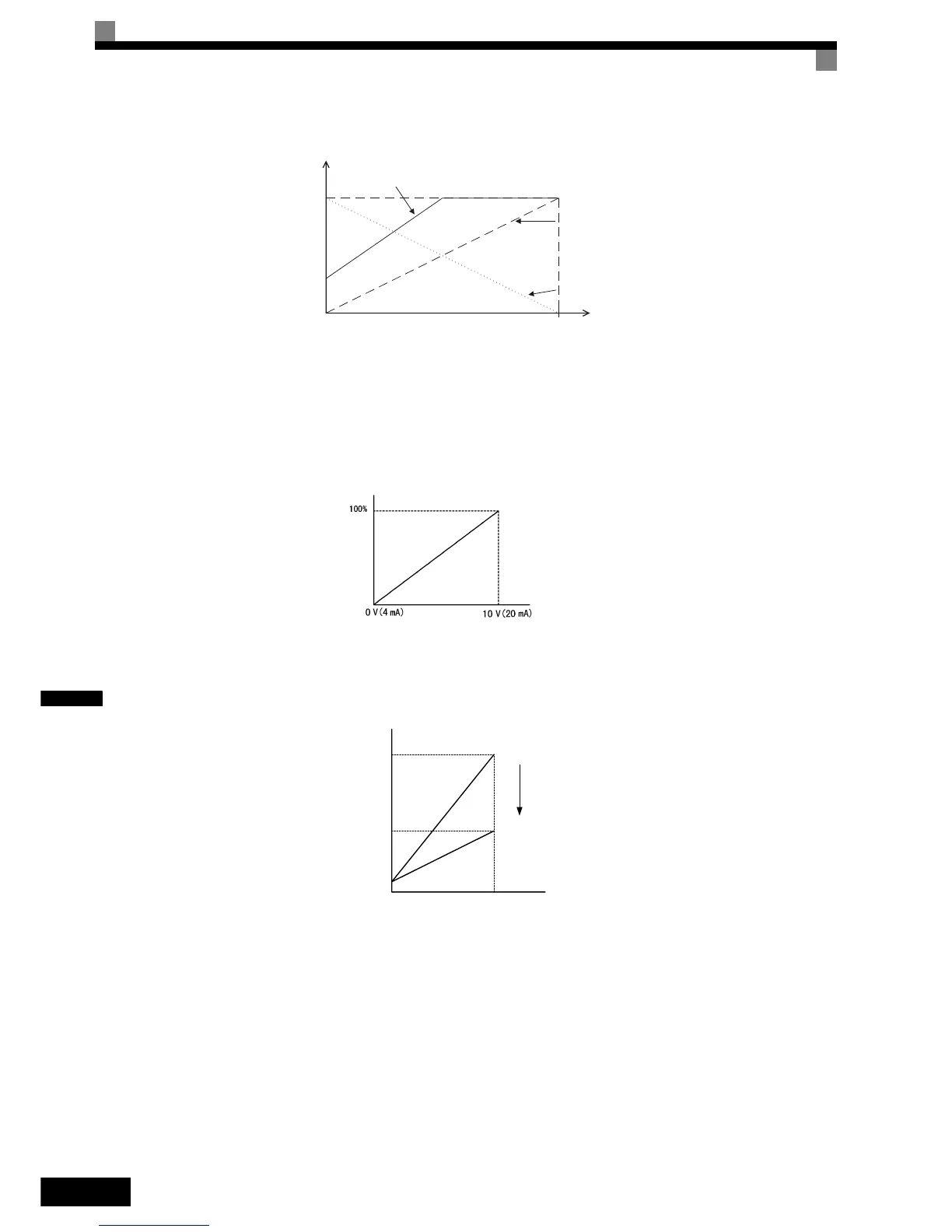
Refer to Fig 6.30 for adjusting the signal using the gain and bias functions.
Fig 6.30 Terminals A1 and A2 Inputs
Adjusting Frequency Gain Using an Analog Input
When H3-09 (H3-05) is set to 1 (frequency gain), the frequency gain can be adjusted using analog input A2
(or channel 3 of AI-14B).
Fig 6.31 Frequency Gain Adjustment (Terminal A2 Input)
The frequency gain for terminal A1 is the product of H3-02 and gain which is input at terminal A2 (or channel
3 of AI-14B). For example, when H3-02 is set to 100% and the terminal A2 (or channel 3 of AI-14B) input is
5 V, the frequency reference gain will be 50%.
Fig 6.32 Frequency Gain Setting Example
Input voltage (current)
10V
(20mA)
0V
(4mA)
0%
100%
Frequency
reference
Gain: 170%
Bias: 30%
Gain: 100%
Bias: 0%
Gain: 0%
Bias: 100%
Frequency gain
Multi-function analog input
terminal A2 input level
0 10 V
100 %
50 %
H3-02
H3-02 x 0.5
Frequency reference
terminal A1 input voltage

 Loading...


