6-30
6
The relationship between the output frequency and the jump frequency reference is shown in Fig 6.35.
Fig 6.35 Jump Frequency
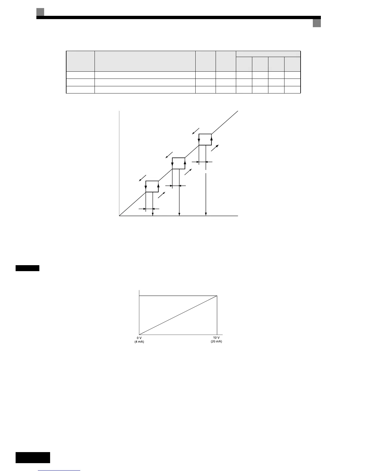
Setting Jump Frequency Reference Using an Analog Input
When parameter H3-09 (analog input A2 function selection) is set to A (jump frequency), the jump frequency
can be changed by the terminal A2 input value (respectively H3-05 and channel 3 of the AI-14B option card).
Fig 6.36 Jump Frequency Setting Using an Analog Input
Setting Precautions
• Set the jump frequencies according to the following formula: d3-01 ≥ d3-02 ≥ d3-03 > Analog input.
• When parameters d3-01 to d3-03 are set to 0 Hz, the jump frequency function is disabled.
Adjusting Pulse Train Input Reference Values
If b1-01 is set to 4 and H6-01 is set to 0, the pulse train input is selected as the frequency reference source. Set
the pulse frequency that is equal to 100% reference in parameter H6-02, and then adjust the gain and bias
accordingly using H6-03 and H6-04.
d3-02 Jump frequency 2 0.0 Hz No A A A A
d3-03 Jump frequency 3 0.0 Hz No A A A A
d3-04 Jump frequency width 1.0 Hz No A A A A
Parameter
No.
Name
Factory
Setting
Change
during
Opera-
tion
Control Methods
V/f
V/f with
PG
Open
Loop
Vector
Closed
Loop
Vector
Output frequency
Frequency reference descending
Jump frequency
width d3-04
Jump frequency reference
Frequency reference ascending
Jump frequency
width d3-04
Jump frequency
width d3-04
Jump
frequency 3
(d3-03)
Jump
frequency 2
(d3-02)
Jump
frequency 1
(d3-01)
Multi-function analog input ter-
minal A2 input level
Max. output frequency
E1-04
Jump frequency

 Loading...


