6-50
6
L6-01 and L6-04 Set Values and Operator Display
The relationship between alarms displayed on the digital operator when overtorque or undertorque is detected,
and the set values in L6-01 and L6-04, is shown in the following table.
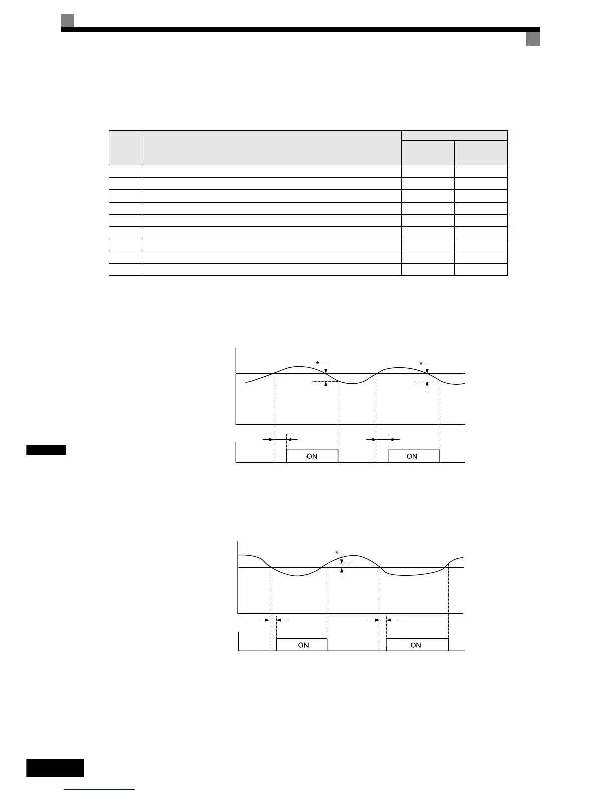
Timing Charts
Fig 6.52 and Fig 6.53 show the timing charts for overtorque and undertorque detection.
Fig 6.52 Overtorque Detection
Fig 6.53 Undertorque Detection
Set
Value
Function
Operator Display
Overtorque/
Undertorque
Detection 1
Overtorque/
Undertorque
Detection 2
0 Overtorque/undertorque detection disabled. – –
1 Overtorque detection only with speed agree; operation continues (warning is output). OL3 flashes OL4 flashes
2 Overtorque detected continuously during operation; operation continues (warning is output). OL3 flashes OL4 flashes
3 Overtorque detection only with speed agree; output is stopped upon detection. OL3 lights up OL4 lights up
4 Overtorque detected continuously during operation; output is stopped upon detection. OL3 lights up OL4 lights up
5 Undertorque detection only with speed agree; operation continues (warning is output). UL3 flashes UL4 flashes
6 Undertorque detected continuously during operation; operation continues (warning is output). UL3 flashes UL4 flashes
7 Undertorque detection only with speed matching; output is stopped upon detection. UL3 lights up UL4 lights up
8 Undertorque detected continuously during operation; output is stopped upon detection. UL3 lights up UL4 lights up
Motor current (output torque)
L6-02 or L6-05
Overtorque detection 1 NO
or overtorque detection 2 NO
*Overtorque detection switch off bandwidth is approximately 10% of the Inverter
rated output current (or motor rated torque).
L6-03 or
L6-06
L6-03 or
L6-06
Motor current (output torque)
L6-02 or L6-05
L6-03 or
L6-06
L6-03 or
L6-06
Undertorque detection 1 NO
or undertorque detection 2 NO
* Undertorque detection switch off bandwidth is approximately 10% of the Inverter
rated output current (or motor rated torque).

 Loading...


