6-72
6
Application Precautions
• Frequency references which use the UP/DOWN commands are limited by the frequency reference upper
and lower limits set in parameters d2-01 to d2-03. In this case the value from the input A1 becomes the fre-
quency reference lower limit. If using a combination of the frequency reference from terminal A1 and the
frequency reference lower limit set in either parameter d2-02 or d2-03, the larger limit value will become
the frequency reference lower limit.
• If the UP/DOWN commands are used as frequency reference and the run command is input the inverter
accelerates to the frequency reference lower limit which is set in d2-02.
• When using UP/DOWN commands, multi-step operations are disabled.
• When d4-01 (Frequency Reference Hold Function Selection) is set to 1, the frequency reference value
using the UP/DOWN functions is stored even after the power supply is turned OFF. When the power sup-
ply is turned ON and the run command is input, the motor accelerates to the frequency reference that has
been stored. To reset (i.e., to 0 Hz) the stored frequency reference, turn ON the UP or DOWN command
while the run command is OFF.
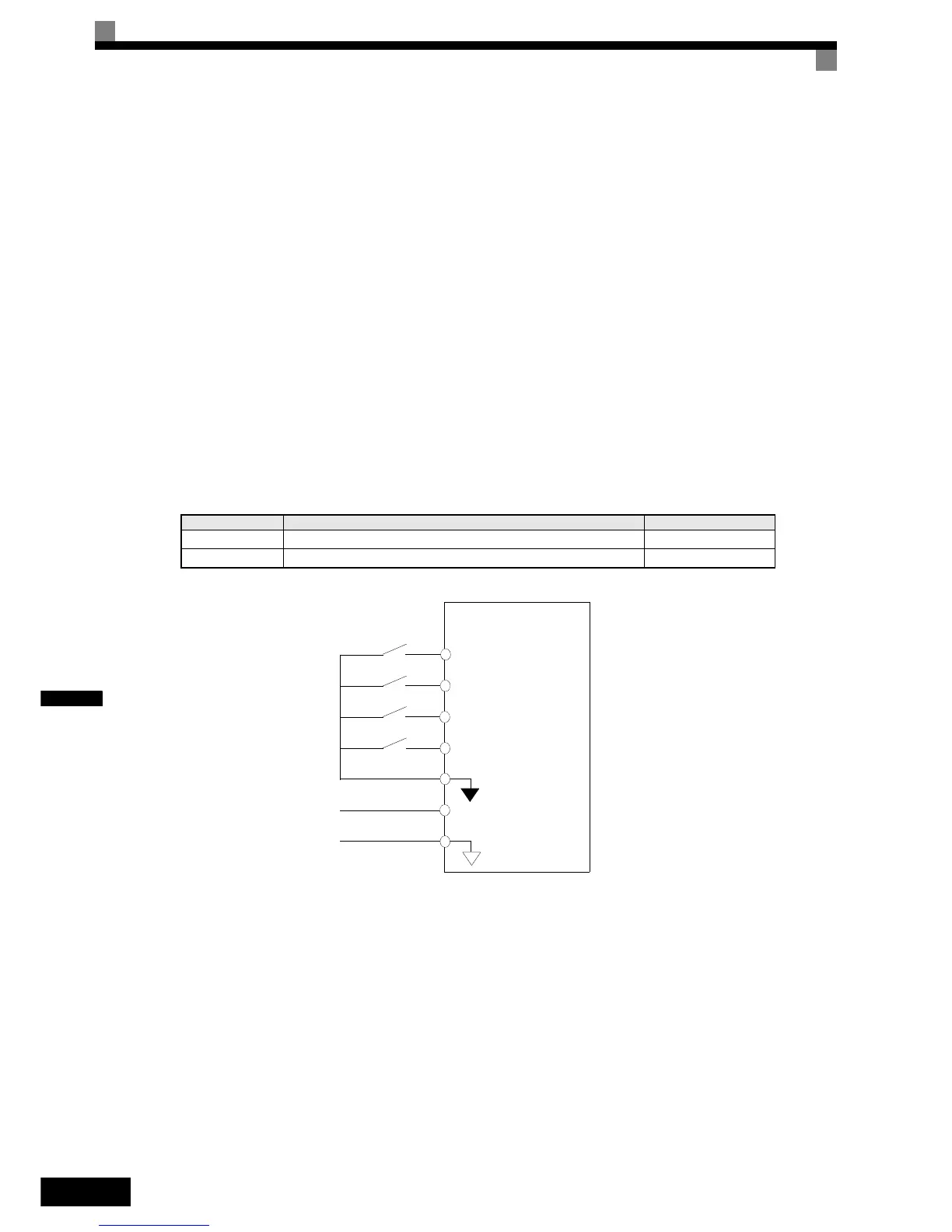
Connection Example and Timing Chart
The time chart and settings example when the UP command is allocated to the digital input terminal S3, and
the DOWN command is allocated to terminal S4, are shown below.
Fig 6.69 Connection Example when UP/DOWN Commands Are Allocated
Parameter Name Set Value
H1-01 Multi-function input (terminal S3) 10
H1-02 Multi-function input (terminal S4) 11
Inverter
Forward operation/
Stop
Reverse operation/
Stop
Up command
Down command
Digital input neu-
tral
Frequency reference lower
limit
0 to 10 V analog sig-
nal
S1
S2
S3
S4
SN
A1
AC

 Loading...


