6-130
6
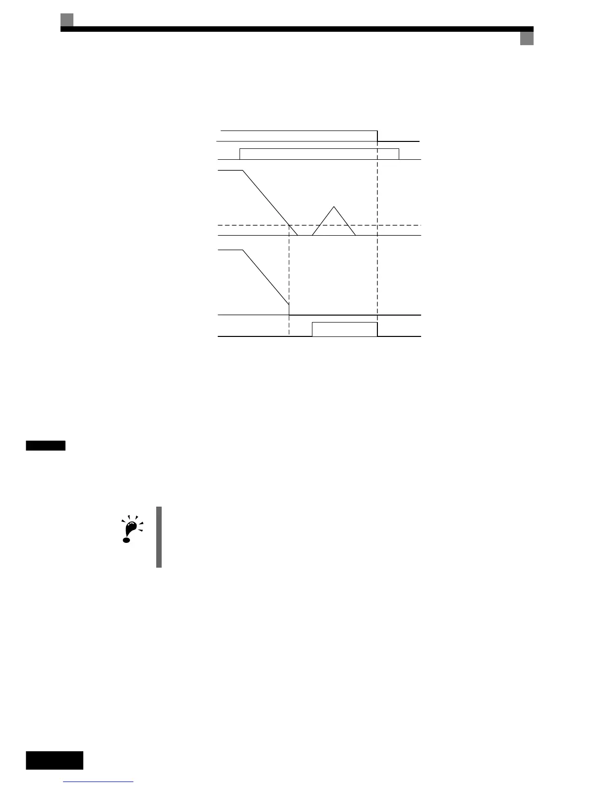
Timing Chart
An example timing chart for the Zero-Servo function showing the input and output signals is given in the fig-
ure below.
Fig 6.90 Time Chart for the Zero-Servo Function
Application Precautions
• Be sure to leave the run command input activated. If the run command is turned OFF, the output will be
interrupted and the zero-servo function will become inactive.
• The holding force of the Zero-Servo position loop can be adjusted in parameter b9-01. The holding force
will increase if the set value is increased. Oscillation and hunting may occur, if the setting is too large.
Adjust b9-01 after adjusting the speed controller (ASR).
• The Zero-Servo detection width is set as the allowable displacement from the Zero-Servo start position.
Set the b9-02 taking the number of displacement pulses from the PG multiplied by 4.
• The Zero-Servo completion signal will be turned OFF when the zero servo command is turned OFF.
IMPORTANT
Do not use the Zero-Servo for extended periods of time with 100% of torque. Inverter faults may
result. If the Zero Servo function shall be used continuously, make sure that the output current dur-
ing the servolock is 50% of the motor current or less.
Run command
OFF
Zero Servo Command
Frequency (speed)
reference
Excitation level
b2-01
Motor speed
Zero Servo End
signal
ON
ON
Zero-servo status
OFF

 Loading...


