6-147
6
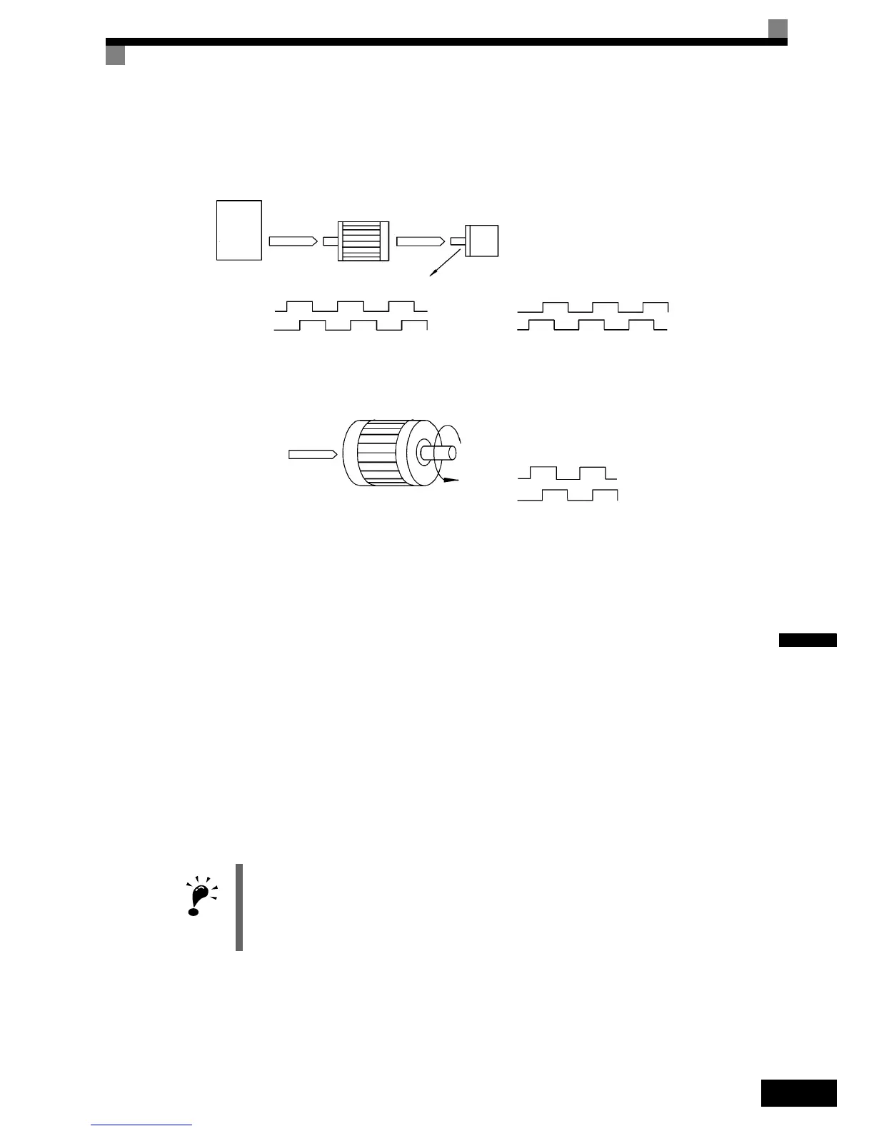
Suit the PG Rotation Direction and Motor Rotation Direction (F1-05)
Parameter F1-05 suits the PG rotation direction to the motor rotation direction. If the motor is rotating for-
wards, set whether it is A-phase leads or B-phase leads.
Generally, the A-phase leads when the rotation direction is counter-clockwise (CCW) seen from the shaft side
(FWD command is input).
Setting Number of Gear Teeth Between PG and Motor (F1-12 and F1-13)
If there are gears between the motor and PG, the gear ratio can be set using F1-12 and F1-13.
When the number of gear teeth has been set, the number of motor rotations within the Inverter is calculated
using the following formula.
No. of motor rotations (r/min.) = No. of input pulses from PG × 60 / F1-01 × F1-13 (No. of gear teeth on PG
side) / F1-12 (No. of gear teeth on motor side)
Integral Operation During Acceleration and Deceleration (F1-07)
You can select whether to enable or disable integral operation during acceleration and deceleration.
To make the motor speed matching the frequency reference as closely as possible even during acceleration and
deceleration, set F1-07 to 1. Refer also to page 6-39, Automatic Speed Regulator (ASR).
IMPORTANT
If F1-07 is set to 1, overshoot or undershoot may occur easily immediately after acceleration and decel-
eration. To minimize the possibility of overshoot or undershoot occurring, set F1-07 to 0.
Inverter
Forward
command
Motor PG (encoder)
Pulse output
A-phase leads when set value = 0
B-phase leads when set value = 1
A-phase A-phase
B-phase
B-phase
Example: Forward rotation of standard motor (PG)
Forward
command
Motor output axis rotates
counter-clockwise during In-
verter forward command.
Rotation
(CCW)
A-phase
B-phase
With the used PG the A-phase leads (CCW) when motor rotation is forward.

 Loading...


