7-4
7
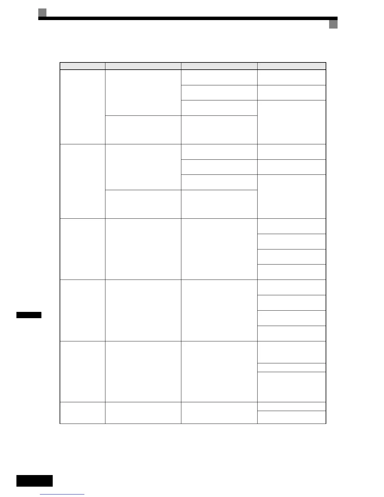
OH
Heatsink Overtemp
Heatsink Overheat
The temperature of the Inverter's
cooling fin exceeded the setting in
L8-02 and L8-03 = 0 to 2.
The ambient temperature is too
high.
Check for dirt build-up on the
fans or heatsink.
There is a heat source nearby.
Reduce the ambient tempera-
ture around the drive.
The Inverter's cooling fan(s)
stopped.
Replace the cooling fan(s).
Inverter's Cooling Fan Fault
(11kW and higher capacity)
This fault is detected when L8-32
is set to 1.
The Inverter's internal cooling fan
has stopped
OH1
Heatsink Max
Temp
Heatsink Overheat
The temperature of the Inverter’s
heatsink exceeded 105 °C.
The ambient temperature is too
high.
Check for dirt build-up on the
fans or heatsink.
There is a heat source nearby.
Reduce the ambient tempera-
ture around the drive.
The Inverter’s cooling fan(s)
stopped.
Replace the cooling fan(s).
Inverter's Cooling Fan Fault
(11kW and higher capacity)
This fault is detected when L8-32
is set to 1.
The Inverter’s internal cooling fan
has stopped
OH3
Motor Overheat 1
Motor Overheating
Detected when the level at A2,
programmed for motor tempera-
ture (Thermistor input, H3-09=E),
exceeds 1.17 V for the time L1-05
and L1-03 = 0 to 2.
Overheating of the motor was
measured by the motor thermistor.
Recheck the cycle time and
the size of the load.
Recheck the accel and decel
times (C1-).
Recheck the V/f pattern
(E1-).
Recheck the motor rated cur-
rent value (E2-01).
OH4
Motor Overheat 2
Motor Overheating
Detected when the level at A2,
programmed for motor tempera-
ture (Thermistor input, H3-09=E),
exceeds 2.34 V for the time L1-05
and L1-03 = 0 to 2.
Overheating of the motor was
measured by the motor thermistor.
Recheck the cycle time and
the size of the load.
Recheck the accel and decel
times (C1-).
Recheck the V/f pattern
(E1-).
Recheck the motor rated cur-
rent value (E2-01).
RH
DynBrk Transistr
Dynamic Braking Resistor
The protection of the heatsink
mounted resistor is activated
when L8-01=1.
This fault is only applicable when
using the 3% duty cycle resistor,
which is mounted on the
Inverter’s heatsink. For all other
resistors, set L8-01=0.
Overhauling load, extended
dynamic braking duty cycle,
defective dynamic braking resis-
tor.
Verify dynamic braking duty
cycle (load, decel times, motor
speed).
Monitor DC bus voltage.
Replace dynamic braking
resistor.
RR
DynBrk Transistr
Dynamic Braking Transistor
The built-in dynamic braking
transistor failed.
Defective or failed dynamic brak-
ing resistor caused braking tran-
sistor damage.
Cycle power to the Inverter.
Replace the Inverter.
Table 7.1 Fault Detection
Display Meaning Probable Causes Corrective Actions

 Loading...


