7-6
7
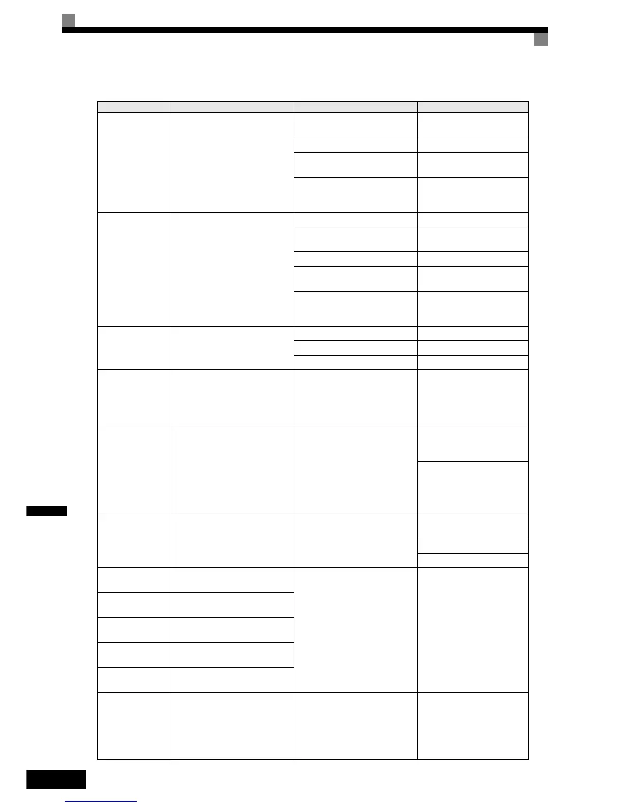
PGO
PG Open
PG Disconnection
Detected when F1-02 = 0 to 2 and
A1-02 = 1 or 3
Detected when no PG (encoder)
pulses are received for a time
longer than the setting in F1-14.
There is a break in the PG wiring.
Fix the broken/disconnected
wiring.
The PG is wired incorrectly. Fix the wiring.
Power is not being supplied to
the PG.
Supply power to the PG
properly.
Wrong brake control sequence
when a brake is used.
Check if the brake is opened
when the RUN command is
applied.
DEV
Speed Deviation
Excessive Speed Deviation
Detected when F1-04 = 0 to 2 and
A1-02 = 1 or 3
The speed deviation is greater
than the setting in F1-10 for a
time longer than the setting F1-11
The load is too large. Reduce the load.
The acceleration time and decel-
eration time are too short.
Lengthen the acceleration
time and deceleration time.
The load is locked. Check the mechanical system.
The settings in F1-10 and F1-11
are not appropriate.
Check the settings in F1-10
and F1-11.
Wrong brake control sequence
when a brake is used.
Check if the brake is opened
when the RUN command is
applied.
SVE
Zero Servo Fault
Zero Servo Fault
The motor position moved during
Zero Servo Operation.
The torque limit is too small. Increase the torque limit.
The load torque is too large. Decrease the load torque.
- Check for signal noise.
CF
Out of Control
Control Fault
A torque limit was reached con-
tinuously for 3 seconds or longer
during a deceleration stop in Open
Loop Vector control.
Motor parameters were not set
properly.
Check the motor parameters.
FBL
Feedback Loss
PID Feedback Lost
This fault occurs when PID feed-
back loss detection is pro-
grammed to fault (b5-12 = 2) and
the PID feedback fell below the
PID Feedback Loss Detection
Level (b5-13) for the PID Feed-
back Loss Detection Time (b5-14)
PID feedback source (e.g. trans-
ducer, sensor, building automa-
tion signal) is not installed
correctly or is not working.
Verify Inverter is pro-
grammed to receive the PID
feedback source signal.
Check to ensure the PID feed-
back source is installed and
working properly.
EF0
Opt External Flt
External fault input from Commu-
nications Option Card
An external fault condition was
present, input from a communica-
tion option card.
Check for an external fault
condition.
Verify the parameters.
Verify communication signals
EF3
Ext Fault S3
External fault at terminal S3
An "external fault" was input
from a multi-function input termi-
nal (S3 to S7).
Eliminate the cause of the
external fault condition.
EF4
Ext Fault S4
External fault at terminal S4
EF5
Ext Fault S5
External fault at terminal S5
EF6
Ext Fault S6
External fault at terminal S6
EF 7
Ext Fault S7
External fault at terminal S7
OPR
Oper Disconnect
Digital Operator Connection Fault
Detected when the digital opera-
tor is removed and the Inverter
receives its RUN command
through the digital operator
(b1-02=0)
The digital operator was removed
during running or the operator
cable is broken.
Check the connection of the
Digital Operator.
Table 7.1 Fault Detection
Display Meaning Probable Causes Corrective Actions

 Loading...


