7-12
7
EF3
Ext Fault S3
(flashing)
External fault at terminal S3
An external fault was input from a
multi-function input terminal
(S3 to S7) that is programmed for
external fault function that alarms
only and continues to run the
Inverter.
Eliminate the cause of the
external fault condition
EF4
Ext Fault S4
(flashing)
External fault at terminal S4
EF5
Ext Fault S5
(flashing)
External fault at terminal S5
EF6
Ext Fault S6
(flashing)
External fault at terminal S6
EF7
Ext Fault S7
(flashing)
External fault at terminal S7
FBL
Feedback Loss
(flashing)
PID Feedback Lost
This fault occurs when PID feed-
back loss detection is pro-
grammed to alarm (b5-12 = 1)
and the PID feedback fell below
the PID Feedback Loss Detection
Level (b5-13) for the PID Feed-
back Loss Detection Time
(b5-14)
PID feedback source (e.g. trans-
ducer, sensor, building automa-
tion signal) is not installed
correctly or is not working
Verify Inverter is pro-
grammed to receive the PID
feedback source signal.
Check to ensure the PID feed-
back source is installed and
working properly.
CE
MEMOBUS Com
Err
(flashing)
MEMOBUS Communications
Alarm
Detected when control data was
not received correctly for two sec-
onds and H5-04 = 3 and
H5-05 = 1.
Connection is broken and/or the
master has stopped the communi-
cation.
Check the connections and all
user-side software configura-
tions.
BUS
Option Com Err
(flashing)
Option Communications Alarm
After initial communication was
established, the connection was
lost.
Connection is broken and/or the
master has stopped the communi-
cation.
Check the connections and all
user-side software configura-
tions.
DNE
Drive Not Enable
(flashing)
Detected when a multi-function
digital input (H1-01 to H1-05) is
programmed for 6A: Drive
Enable.
The Inverter does not have the
enable command when the RUN
command is applied. This alarm
stops the motor.
Enable command was lost while
the Inverter was running.
Check the wiring of the input
terminal and the external
sequence of the enable signal.
The RUN command was applied
prior to the enable signal.
Apply and maintain the enable
command before applying the
RUN command.
Ext Run Active
Cannot Reset
Detected when a RESET com-
mand is input while the RUN
command is still active
The RUN command has not been
removed and a RESET command
is input by digital input or by the
RESET button on the digital oper-
ator.
Remove the RUN signal first
and reset the fault.
CALL
ComCall
(flashing)
Communications on Standby
Communication has not yet been
established.
Connection was not made prop-
erly or user software was not con-
figured to the proper baud rate or
configuration (e.g. Parity).
Check the connections and all
user-side software configura-
tions.
FAN
Cooling FAN Err
(flashing)
Inverter’s Cooling Fan Alarm
An Inverter’s cooling fan fault
was detected.
This alarm is detected when
L8-32 is set to 0.
The Inverter’s cooling fan has
stopped
Replace the cooling fan.
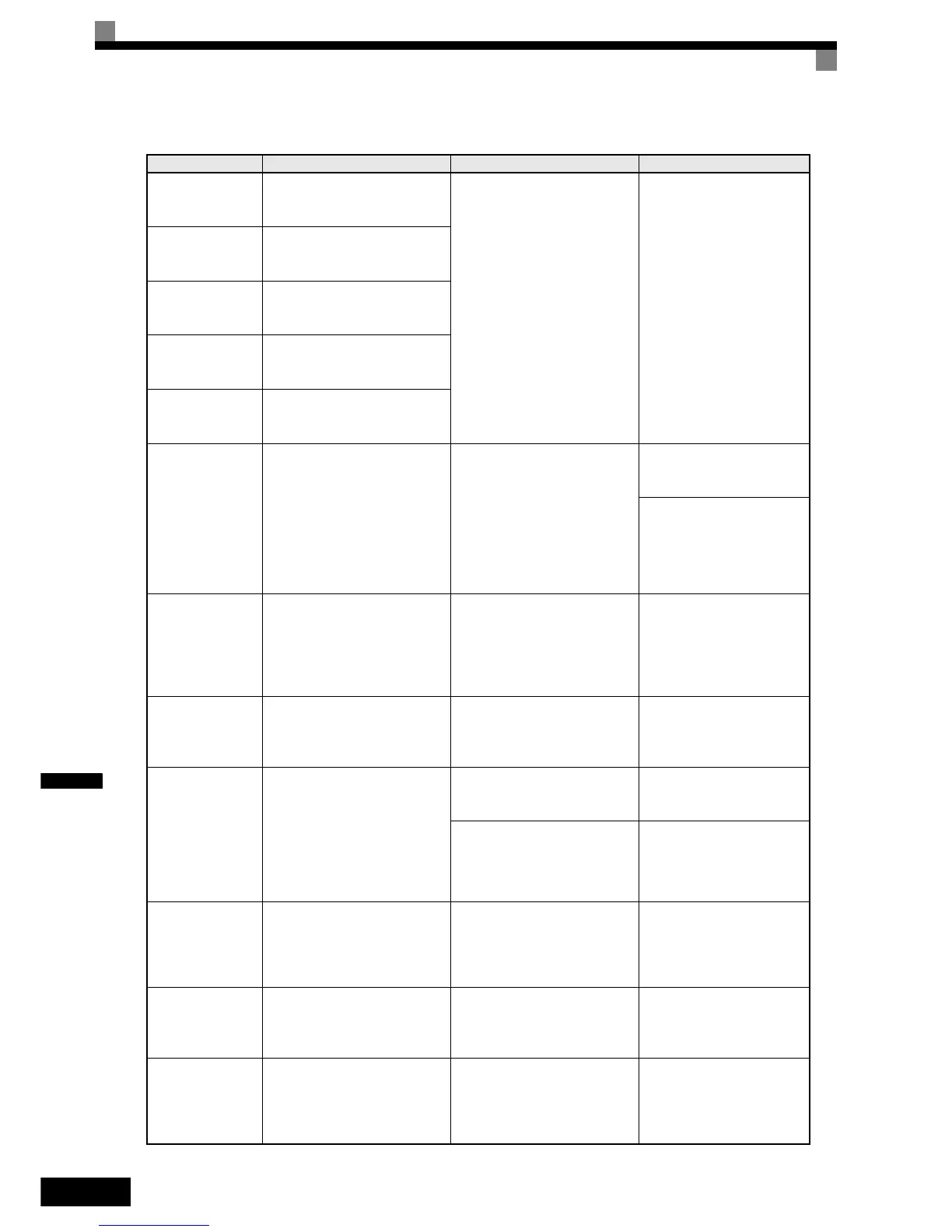
Table 7.2 Alarm Detection
Display Meaning Probable causes Corrective Actions

 Loading...


