3-3
3
* Except in diagrams, Keys are referred to the key names listed in the above table.
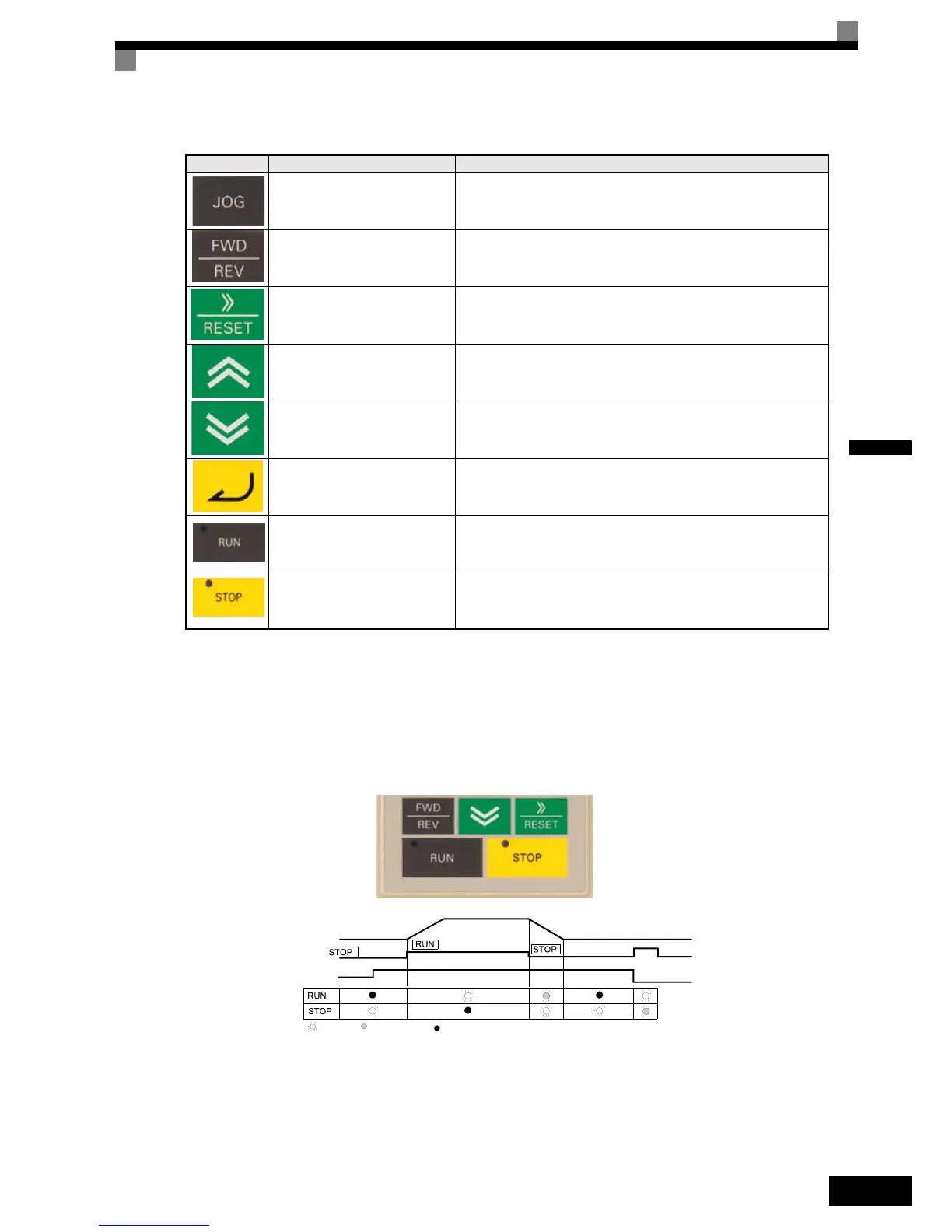
There are indicators on the upper left of the RUN and STOP keys on the Digital Operator. These indicators
will light and flash to indicate operating status.
The RUN key indicator will flash and the STOP key indicator will light during initial excitation or DC brak-
ing. The relationship between the indicators on the RUN and STOP keys and the Inverter status is shown in
Fig 3.2.
Fig 3.2 RUN and STOP Indicators
JOG Key
Enables jog operation when the Inverter is operated from the Digital
Operator.
FWD/REV Key
Selects the rotation direction of the motor when the Inverter is oper-
ated from the Digital Operator.
Shift/RESET Key
Sets the active digit when programming parameters.
Also acts as the Reset key when a fault has occurred.
Increment Key
Selects menu items, sets parameter numbers, and increments set val-
ues.
Used to move to the next item or data.
Decrement Key
Selects menu items, sets parameter numbers, and decrements set val-
ues.
Used to move to the previous item or data.
DATA/ENTER Key
Pressed to enter menu items, parameters, and set values.
Also used to switch from one screen to another.
RUN Key
Starts the Inverter operation when the Inverter is being controlled by
the Digital Operator.
STOP Key
Stops Inverter operation.
This key can be enabled or disabled when operating from the control
circuit terminal by setting parameter o2-02.
Table 3.1 Key Functions (Continued)
Key Name Function
Inverter output frequency
Frequency setting
: Light up
: Blinking
: Not light up

 Loading...


