EasyManua.ls Logo

Optopol SOCT Copernicus + - Page 89

Optopol SOCT Copernicus +
200 pages
Print Icon
To Next Page IconTo Next Page
To Previous Page IconTo Previous Page
Loading...
SOCT Copernicus PLUS - Service Manual
89
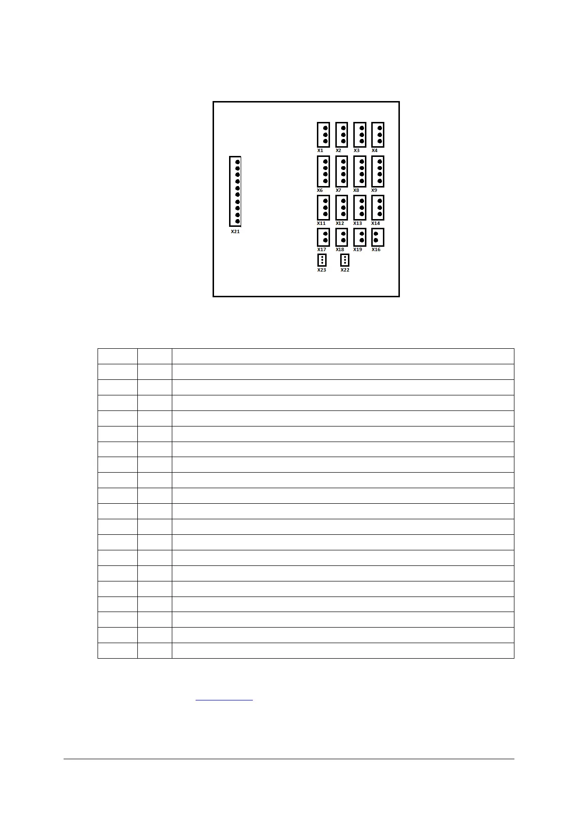
8. Connect all plugs to the proper sockets according to below description.
Transitional board 151-527.
Socket
Plug
Description
X1
---
Not Connected
X2
X2
+12V, CPU master 151-506
X3
X3
+12V, Camera AviivA Power supply
X4
X4
+12V, Eye preview camera power supply
X6
X6
+/- 24V, Galvo scanners power supply X
X7
X7
+/- 24V, Galvo scanners power supply Y
X8
X8
+/- 24V, Motors module 151-517 power supply
X9
---
Not Connected
X11
---
Not Connected
X12
X12
+12V, CPU slave 151-512
X13
X13
+12V, CPU master 151-506
X14
X14
+12V, Spectrometer servomechanism module
X16
X16
+5V, Inphenix SLED power supply
X17
X17
+5V, CPU slave 151-512
X18
X18
+5V, CPU master 151-506
X19
X19
+5V, Power resistor
X21
X21
Main source
X22
X22
Y scanner voltage verification
X23
X23
X scanner voltage verification
9. Close the cover (see: Closing cover).

Table of Contents

Related product manuals