SOCT Copernicus PLUS - Service Manual
13. Connect all plugs to transitional board.
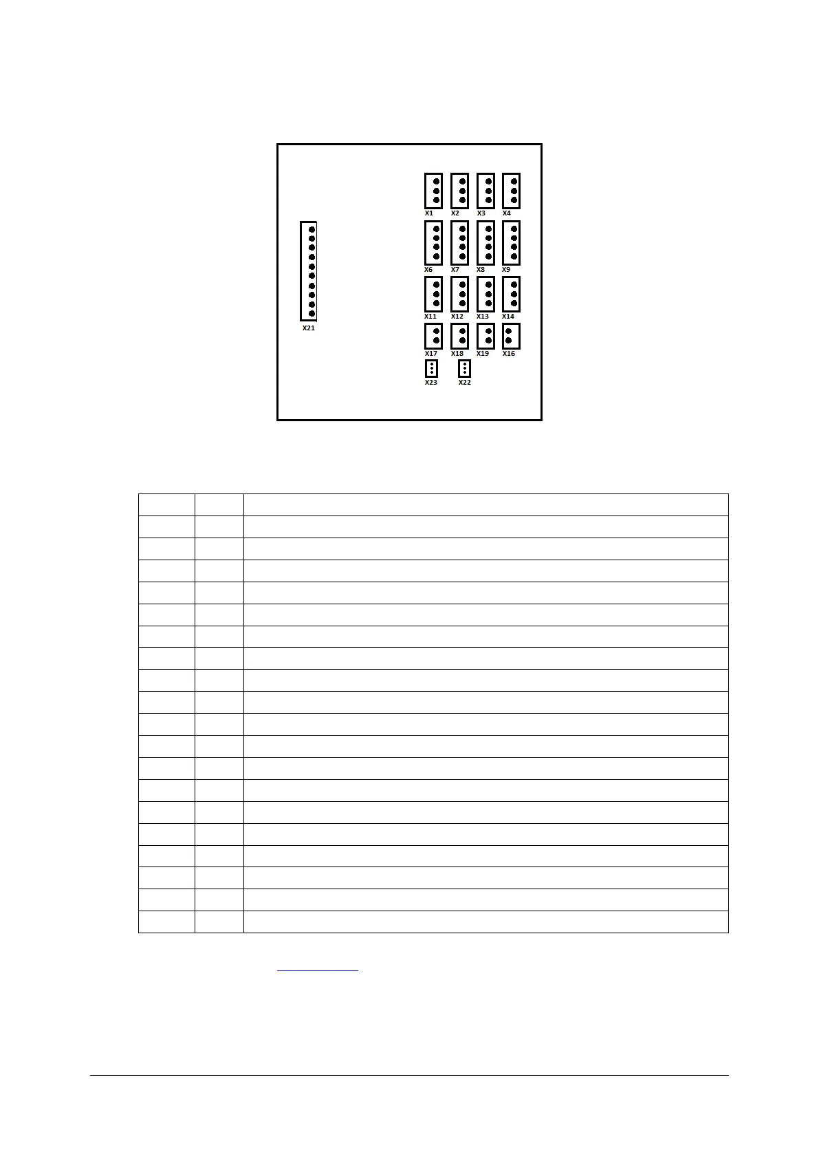
Transitional board 151-527.
+12V, Camera AviivA Power supply
+12V, Eye preview camera power supply
+/- 24V, Galvo scanners power supply X
+/- 24V, Galvo scanners power supply Y
+/- 24V, Motors module 151-517 power supply
+12V, Spectrometer servomechanism module
+5V, Inphenix SLED power supply
Y scanner voltage verification
X scanner voltage verification
14. Close the cover (see: Closing cover).
It is necessary to contact with Optopol Technology Sp. z o.o. Service Division if the device have
S/N: 154011/I; 154013/I; 154014/I; 154015/I; 154016/J; 154017/J; 154018/J.