>
--I
ca
~
w
en
en
«
en
Cl
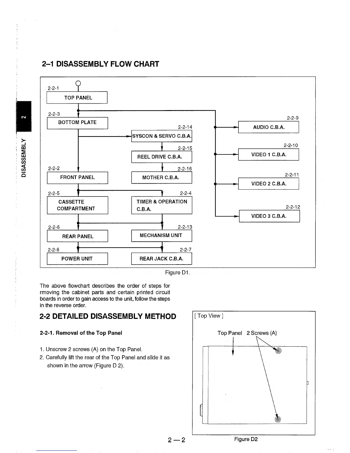
2-1 DISASSEMBLY FLOW CHART
2-2-1
9
TOP PANEL
2-2-3
t
BOTTOM PLATE
2-2-14
SYSCON & SERVO C.B.A.
2-2-15
REEL
DRIVE C.B.A.
2-2-2
2-2-16
FRONT PANEL
MOTHER C.B.A.
2-2-5
, ,
2-2-4
CASSETTE
TIMER
& OPERATION
COMPARTMENT
C.B.A.
2-2-6
2-2-13
REAR PANEL
MECHANISM UNIT
2-2-8
,
1
2-2-7
POWER UNIT REAR
JACK
C.B.A.
Figure
D1.
The above flowchart describes the order of steps for
rmoving the cabinet parts and certain printed circuit
boards
in
order to gain access to the unit, follow the steps
in
the reverse order.
2-2 DETAILED DISASSEMBLY METHOD
2-2-1. Removal
of
the
Top Panel
1.
Unscrew 2 screws (A) on the Top Panel.
2.
Carefully lift the rear of the Top Panel and slide
it
as
shown
in
the arrow (Figure D 2).
2-2
2-2-9
I
I I
AUDIO C.B.A.
2-2-10
I
I
VIDEO 1 C.B.A.
I
2-2-11
I
VIDEO 2 C.B.A.
I I
2-2-12
I
I
VIDEO 3 C.B.A.
I
[Top
View 1
Top Panel 2 Screws
(A)
Figure D2