:!:
Cl)
z
«
::r:
u
w
~
3-5-2. REPLACEMENT OF THE LOWER
CYLINDER UNIT
1.
Unscrew the 2 screws
and
remove the Head Amp.
2.
Remove the Cleaning
rod
from bottom side.
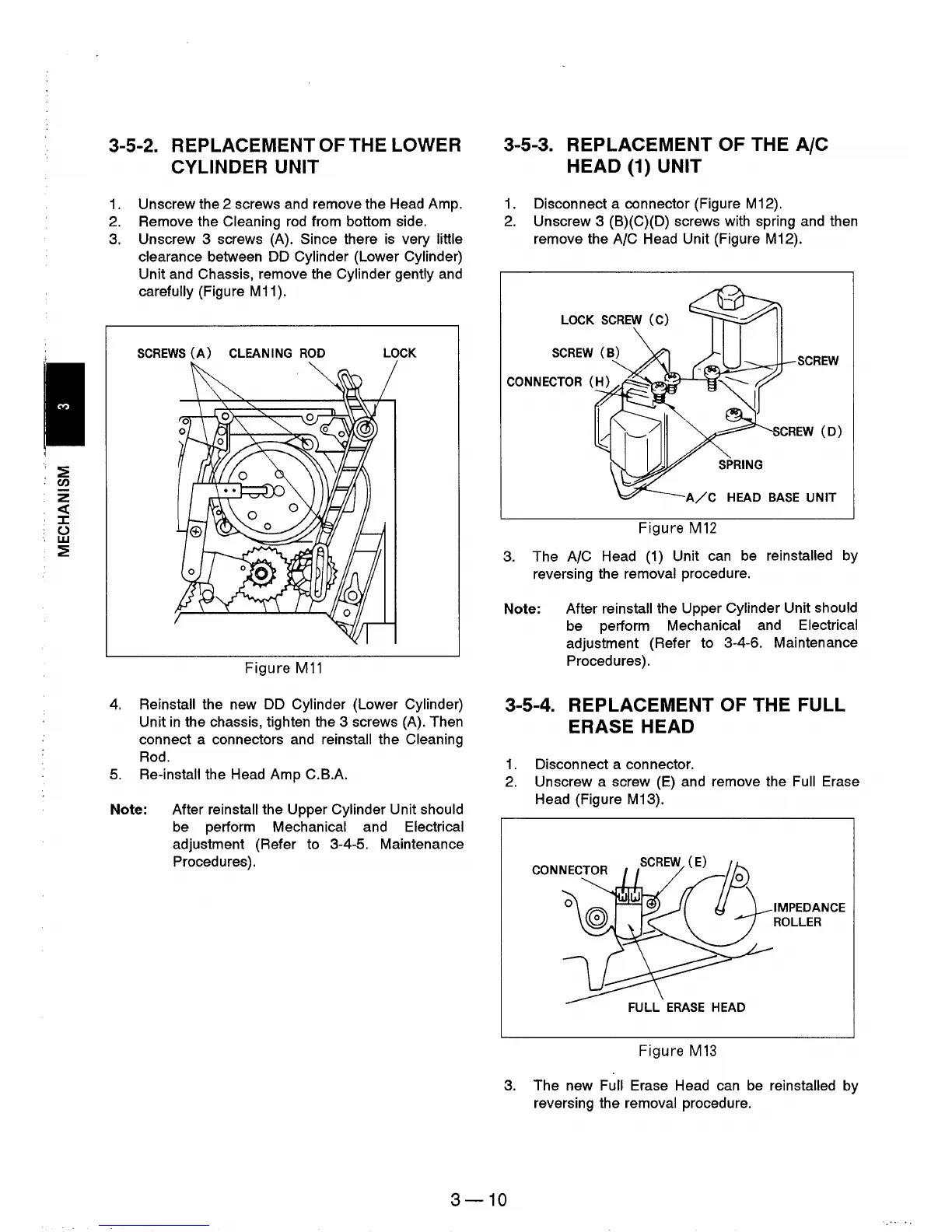
3. Unscrew 3 screws (A). Since there
is
very little
clearance
between DD Cylinder (Lower Cylinder)
Unit and Chassis, remove the Cylinder gently
and
carefully (Figure M11).
SCREWS
(A)
CLEANING
ROD
LOCK
Figure
M11
4.
Reinstall the new DD Cylinder (Lower Cylinder)
Unit
in
the chassis, tighten the 3 screws (A). Then
connect a connectors and
reinstall the Cleaning
Rod.
5.
Re-install the Head Amp
C.BA
Note: After reinstall the Upper Cylinder Unit should
be perform Mechanical and Electrical
adjustment (Refer to 3-4-5. Maintenance
Procedures).
3-5-3. REPLACEMENT OF THE
AIC
HEAD (1) UNIT
1.
Disconnect a connector (Figure M12).
2.
Unscrew 3 (B)(C)(D) screws with spring and then
remove the
AIC Head Unit (Figure M12).
LOCK
SCREW
(C)
SCREW
(B)
~~~.::>~-
SCREW
SPRING
HEAD
BASE
UNIT
Figure M
12
3.
The AIC Head (1) Unit can be reinstalled by
reversing the
removal procedure.
Note: After
reinstall the Upper Cylinder Unit should
be perform Mechanical and Electrical
adjustment (Refer to 3-4-6. Maintenance
Procedures).
3-5-4. REPLACEMENT OF THE FULL
ERASE HEAD
1.
Disconnect a connector.
2.
Unscrew a screw
(E)
and remove the Full Erase
Head (Figure M13).
Figure
M13
IMPEDANCE
ROLLER
3.
The new Full Erase Head can
be
reinstalled by
reversing the
removal procedure.
3-10