~
en
z
«
:::I:
U
w
~
3-6-13. MEASUREMENT AND
ADJUSTMENT
OF THE
BRAKE
TORQUE
«TOOL»
Torque Gauge
Adaptor for Gauge
VFK0133
VFK0134
1.
2.
3.
4.
Remove the top cover and the cassette
compartment.
Attach the adapter to the torque gauge and
place
the deck
in
STOP mode (Sub loading mode).
Place the torque gauge
on
the reel table as shown
in
Figure M36-A. The weight of the gauge should
not rest
on
the reel table.
Turn the torque gauge
in
the direction indicated
in
Figure M36-B until the brake begins slipping and
read the gauge.
Figure M36-A Measuring Method
B~A A~B
SUPPLY REEL
TAKEUP
REEL
A B
Takeup
more than
50g-cm
more than
550g-cm
Supply
more than
50g-cm
Figure M36-B Specification
of
Btake Torque
5.
If it
is
out
of
specification, replace the Brake
Spring.
Note:
If
the proper brake torque cannot be obtained
by
replacing the Brake Spring, clean the
braking surface of the
reel table with a soft
cloth and re-measure the brake torque.
If
its
still out
of
specification, replace the Main
Brake
(S) or (T) Unit.
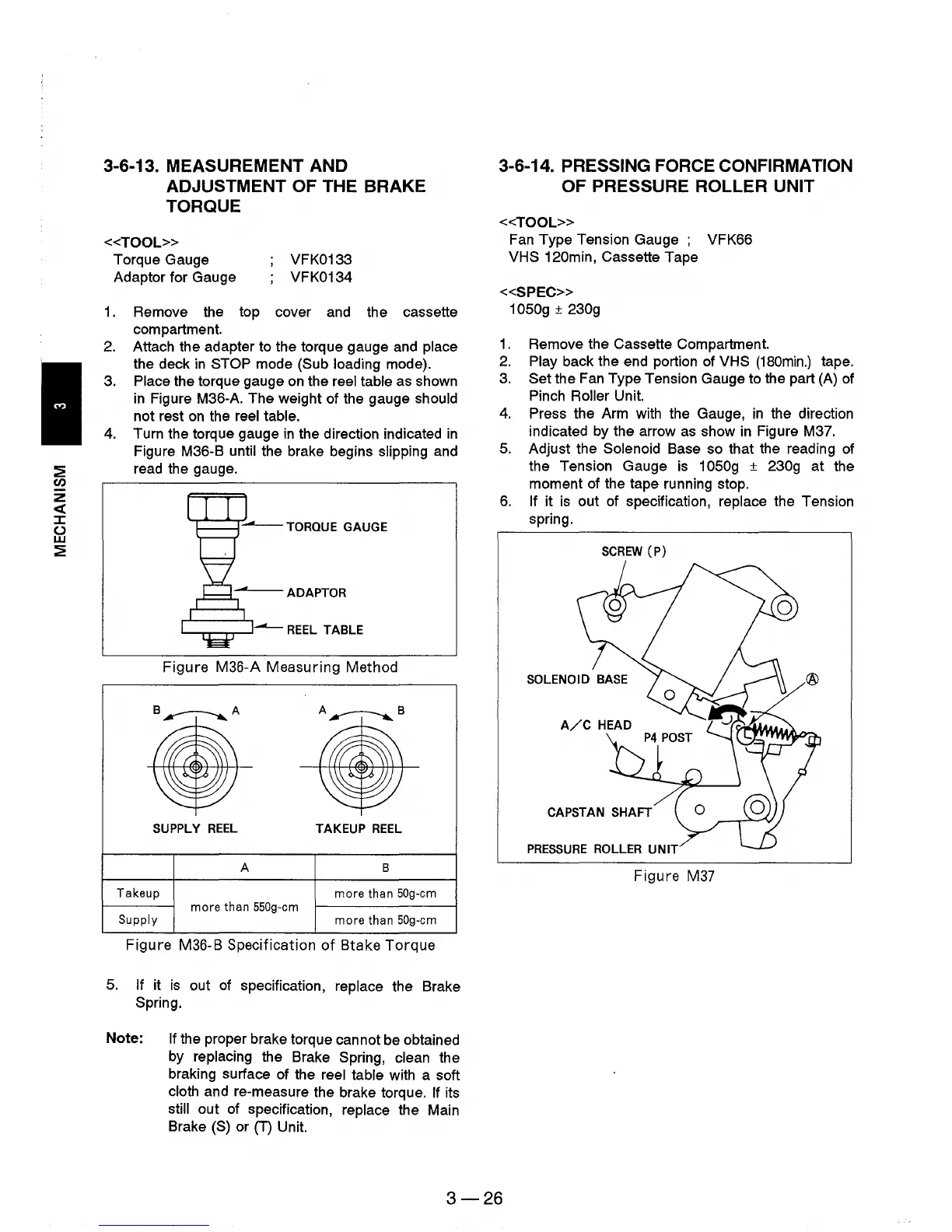
3-6-14. PRESSING FORCE CONFIRMATION
OF PRESSURE
ROLLER UNIT
«TOOL»
Fan
Type Tension Gauge VFK66
VHS
120min, Cassette Tape
«SPEC»
1050g ± 230g
1.
Remove the Cassette Compartment.
2.
Play back the end portion of VHS
(180min.)
tape.
3.
Set the
Fan
Type Tension Gauge to the part (A)
of
Pinch Roller Unit.
4.
Press the Arm with the Gauge,
in
the direction
indicated by the arrow
as
show
in
Figure M3?
5.
Adjust the Solenoid Base so that the reading of
the Tension Gauge
is
1 050g ± 230g at the
moment of the tape running stop.
6.
If it
is
out of specification, replace the Tension
spring.
SCREW
(P)
CAPSTAN
SHAFT
PRESSURE
ROLLER
UNIT
Figure M37
3-26