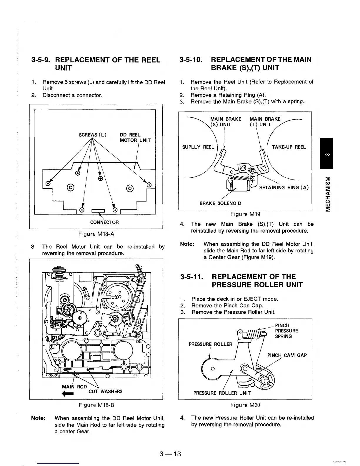
3-5-9. REPLACEMENT OF THE REEL
UNIT
1.
Remove 6 screws
(L)
and carefully lift the
DD
Reel
Unit.
2.
Disconnect a connector.
SCREWS
(L)
CONNECTOR
Figure M18-A
3. The Reel Motor Unit can be re-installed by
reversing the removal procedure.
MAIN
ROD
~
CUT
WASHERS
Figure M18-B
Note: When assembling the DD Reel Motor Unit,
side the Main Rod to far
left side by rotating
a center Gear.
3-5-10. REPLACEMENT OF THE MAIN
BRAKE (S),(T) UNIT
1.
Remove the Reel Unit (Refer
to
Replacement of
the
Reel Unit).
2.
Remove a Retaining Ring (A).
3.
Remove the Main Brake (S),(T) with a spring.
RETAINING RING
(A)
BRAKE SOLENOID
Figure M
19
4.
The new Main Brake (S),(T) Unit
can
be
reinstalled by reversing the removal procedure.
Note: When assembling the DD
Reel Motor Unit,
slide the Main Rod to far left side by rotating
a Center Gear (Figure M19).
3-5-11. REPLACEMENT OF THE
PRESSURE ROLLER UNIT
1.
Place the deck
in
or EJECT mode.
2.
Remove the Pinch Can Cap.
3.
Remove the Pressure Roller Unit.
PINCH CAM GAP
PRESSURE
ROLLER
UNIT
Figure
M20
4.
The new Pressure Roller Unit can be re-installed
by reversing the removal procedure.
3-13