:E
en
Z
«
J:
u
w
:E
3-6-6. COARSE ADJUSTMENT OF THE
AIC HEAD HORIZONTAL POSITION
(X-VALUE)
Note: This procedure should be performed only
when the A/C head
is
replaced, and after
performing the tape interchangeability
adjustment.
«TOOL»
H-Position Adjustment Screwdriver; VFK0328
Alignment Tape ;
VFM8180HADH
1.
Connect a scope
CH1
to Video
RF
Test Terminal
(TP6 of the Video 1 C.B.A.) and a scope CH2
to
Normal Audio CH2 output
on
the Rear Jack.
2.
Playback
the
1
position
(Monoscope
1
and
AudiolEvery 10-the field is skipped) of the
Alignment tape
VFM8180HADH.
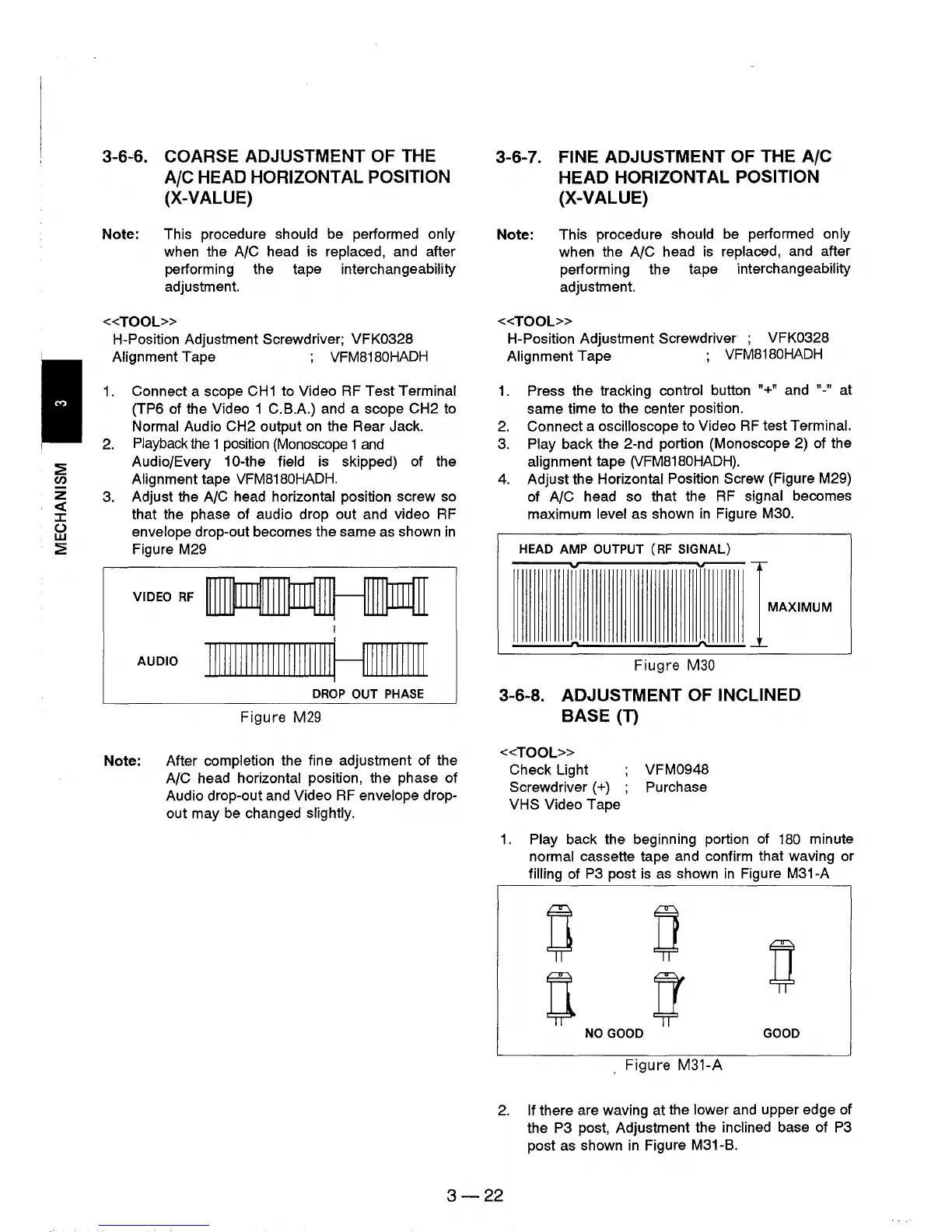
3.
Adjust the A/C head horizontal position screw so
that the phase of audio drop out and video
RF
envelope drop-out becomes the same
as
shown
in
Figure M29
VIDEO
RF
AUDIO
IIIIIIIIIIIIIIIIIIIIIIIIHIIIIIIIIIIII
DROP
OUT
PHASE
Figure
M29
Note: After completion the fine adjustment of the
A/C head horizontal position, the phase of
Audio drop-out and Video
RF
envelope drop-
out may
be
changed slightly.
3-6-7. FINE ADJUSTMENT OF THE AIC
HEAD HORIZONTAL POSITION
(X-VALUE)
Note: This procedure should be performed only
when the A/C head
is
replaced, and after
performing the tape interchangeability
adjustment.
«TOOL»
H-Position Adjustment Screwdriver ; VFK0328
Alignment Tape ;
VFM8180HADH
1.
Press the tracking control button
"+"
and "-" at
same time
to
the center position.
2.
Connect a oscilloscope to Video
RF
test Terminal.
3.
Play back the 2-nd portion (Monoscope 2) of the
alignment tape
(VFM8180HADH).
4.
Adjust the Horizontal Position Screw (Figure M29)
of
NC
head so that the
RF
signal becomes
maximum level as shown
in
Figure M30.
HEAD
AMP
OUTPUT
(RF SIGNAL)
..,
v---
IMAXIMUM
n
~
Fiugre
M30
3-6-8. ADJUSTMENT OF INCLINED
BASE(T)
«TOOL»
Check Light VFM0948
Screwdriver (+) Purchase
VHS
Video Tape
1.
Play back the beginning portion of
180
minute
normal cassette tape and confirm that waving or
filling of
P3
post
is
as
shown
in
Figure M31-A
0
0
0
n
n
NO
GOOD
GOOD
. Figure
M31-A
2.
If there are waving at the lower
and
upper edge of
the
P3 post, Adjustment the inclined base of
P3
post as shown
in
Figure M31-B.
3-22