CH1
CH2
Figure M28-C
D.
TILT and AZIMUTH ADJUSTMENT OF
AIC
HEAD
1.
Adjust the screw
(C)
and
(B)
so that
CH1
and CH2
output levels become maximum, these phase of
both channels much at the same time (Figure
M28-D). During this adjustment the Lock screw
(D)
dose not touch the A/C Head Base
as
shown
in
Figures M28-E.
CH1
CH2
I
iOMAXIMUM
I
I
i
OMAXIMUM
Figure M28-0
Lock
Screw
(D)
Screw
(B)
______
Screw
(C)
~
AIC
Head Base
Figure M28-E
E.
ADJUSTMENT OF LOCK SCREW
1.
Turn the screw
(C)
to clockwise so that the
difference of phase
of
both channels become 180
degrees
as
shown
in
Figure M28-F.
2.
Tighten the Lock screw
(D)
so
that these phase of
both channels match
as
shown
in
Figure M28-F.
CH1
o·
1180·
I
CH2
Figure M28-F
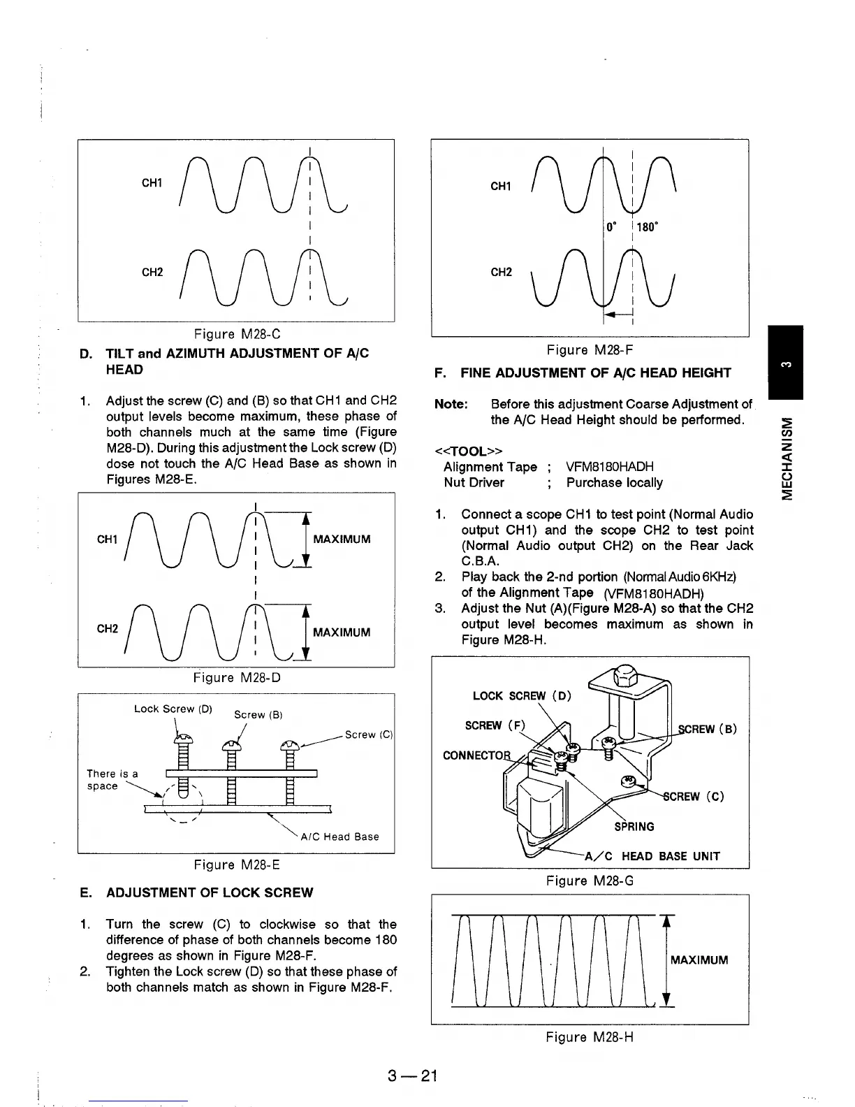
F.
FINE ADJUSTMENT OF AlC HEAD HEIGHT
Note: Before this adjustment Coarse Adjustment of
the
A/C Head Height should
be
performed.
<<TOOL»
Alignment Tape
Nut Driver
VFM8180HADH
Purchase locally
1.
Connect a scope
CH1
to test point (Normal Audio
output
CH
1) and the scope CH2 to test point
(Normal Audio output CH2)
on
the Rear Jack
C.B.A.
2.
Play back the 2-nd portion (NormaIAudio6KHz)
of the Alignment Tape (VFM8180HADH)
3.
Adjust the Nut
(A)
(Figure M28-A)
so
that the CH2
output level becomes maximum
as
shown
in
Figure M28-H.
LOCK
SCREW
(D)
REW
(B)
SPRING
A/C
HEAD
BASE
UNIT
Figure M28-G
MAXIMUM
Figure
M28-H
3-21