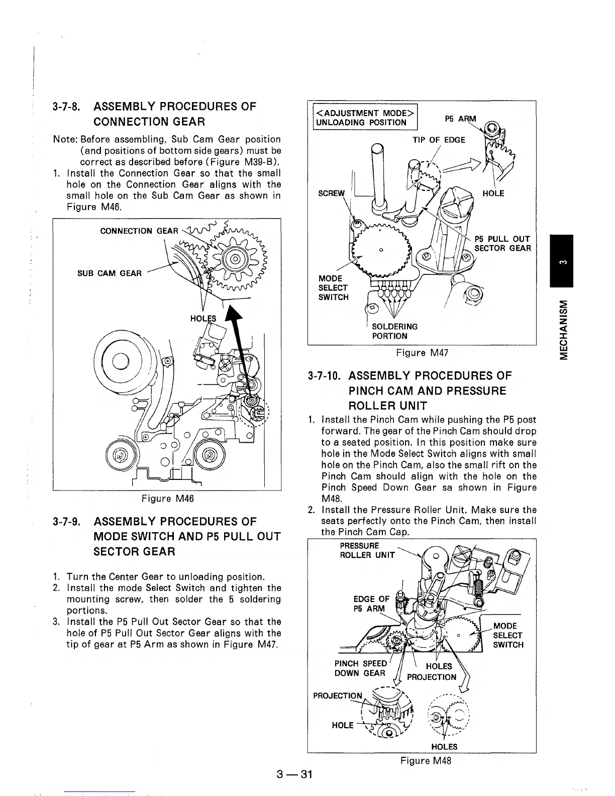
3-7-8.
ASSEMBLY PROCEDURES OF
CONNECTION
GEAR
Note: Before assembling, Sub Cam Gear position
(and positions
of
bottom
side gears) must
be
correct as described before
(Figure
M39-B).
1.
Install the Connection Gear
so
that
the small
hole
on
the Connection Gear aligns with the
small hole
on
the Sub Cam Gear as shown
in
Figure
M46.
SUB CAM GEAR
Figure
M46
3-7-9.
ASSEMBLY PROCEDURES OF
MODE
SWITCH
AND
P5
PULL
OUT
SECTOR GEAR
1.
Turn
the Center Gear
to
unloading position.
2.
Install
the mode Select Switch and tighten the
mounting screw, then solder the 5 soldering
portions.
3.
Install the
P5
Pull Out Sector Gear
so
that
the
hole
of
P5
Pull Out Sector Gear aligns with the
tip
of
gear
at
P5
Arm
as
shown
in
Figure
M47.
<ADJUSTMENT
MODE>
UNLOADING POSITION
MODE
SELECT
SWITCH
SOLDERING
PORTION
P5
ARM
Figure
M47
3-7-10.
ASSEMBLY PROCEDURES OF
PINCH
CAM
AND
PRESSURE
ROLLER
UNIT
1.
Install the Pinch Cam while pushing the
P5
post
forward.
The gear
of
the Pinch Cam should
drop
to
a seated position. In
this
position make sure
hole
in
the Mode Select Switch aligns
with
small
hole
on
the Pinch Cam, also the small
rift
on
the
Pinch Cam should align
with
the hole on the
Pinch
Speed
Down Gear
sa
shown
in
Figure
M48.
2.
Install the Pressure Roller Unit. Make sure the
seats perfectly
onto
the Pinch Cam, then install
the Pinch Cam Cap.
PRESSURE
ROLLER
UNIT
PROJECTION
HOLES
Figure
M48
MODE
SELECT
SWITCH
3-31
~
CIJ
z
«
::z::
()
w
~