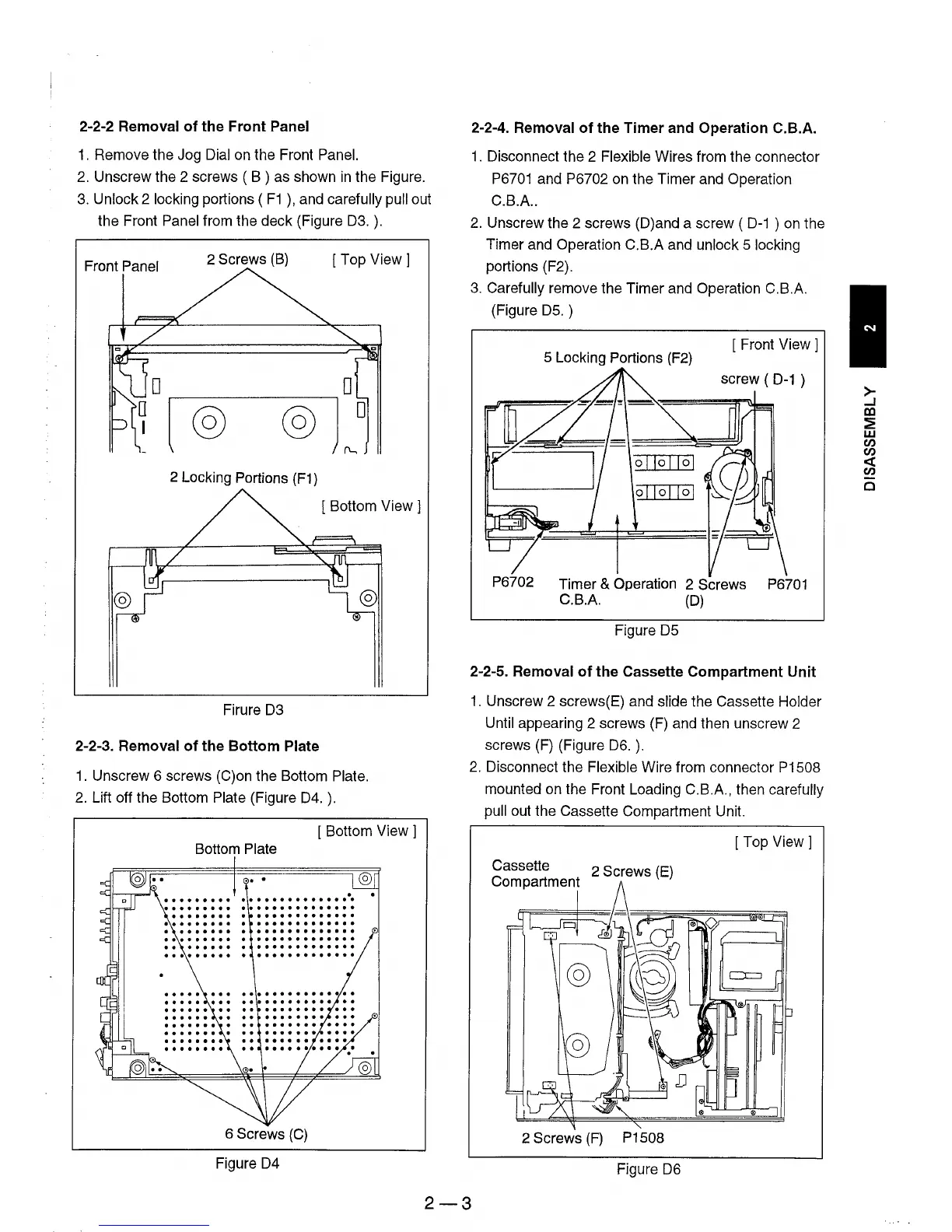
2-2-2 Removal
of
the
Front
Panel
1.
Remove the Jog Dial on the Front Panel.
2.
Unscrew the 2 screws ( B ) as shown
in
the Figure.
3.
Unlock 2 locking portions (
F1
),
and carefully pull out
the Front
Panel from the deck (Figure
D3.
).
Front Panel
2 Screws
(B)
[Top
View 1
@ @
2 Locking Portions
(F1)
[ Bottom View 1
Firure D3
2-2-3. Removal
of
the
Bottom
Plate
1.
Unscrew 6 screws (C)on the Bottom Plate.
2.
Lift off the Bottom Plate (Figure
D4.
).
[ Bottom
View]
Bottom Plate
6 Screws
(C)
Figure D4
2-2-4. Removal
of
the
Timer and Operation C.B.A.
1.
Disconnect the 2 Flexible Wires from the connector
P6701
and P6702 on the Timer and Operation
C.B.A
..
2.
Unscrew the 2 screws
(D)
and a screw (
D-1
)
on
the
Timer and Operation C.B.A and
unlock 5 locking
portions (F2).
3.
Carefully remove the Timer and Operation C.B.A.
(Figure
D5.
)
5 Locking Portions
(F2)
[ Front
View]
screw (
D-1
)
01101101
P6702 Timer & Operation 2 Screws
P6701
C.B.A.
(D)
Figure D5
2-2-5. Removal
of
the
Cassette Compartment
Unit
1.
Unscrew 2 screws(E) and slide the Cassette Holder
Until
appearing 2 screws (F) and then unscrew 2
screws (F) (Figure
D6.
).
2.
Disconnect the Flexible Wire from connector P1508
mounted on the Front Loading C.B.A., then carefully
pull
out the Cassette Compartment Unit.
[Top
View]
Cassette 2 Screws
(E)
Compartment
2 Screws
(F)
P1508
Figure
D6
2-3
>-
-I
ca
~
w
(/)
(/)
«
(/)
c