1:2
en
3-7-11.
ASSEMBLY PROCEDURES OF
GEAR BASE
UNIT
1.
Install
the Gear
Base
Unit
and screw 4 screws
(F)
as shown in Figure
M49.
SCREWS
(F)
z Figure
M49
ioe(
.::J:
u Note: The Gear
Base
Unit
has 2 gears and
worm
~
shaft. There is no adjustment
for
these gears.
3-6-12.
REINSTALLATION
OF CASSETTE
COMPARTMENT
When you reinstall the cassette compartment, the
position adjustment
of
mechanism is necessary
for
correct operation,
as
follows.
A. Confirmation of
STOP
Alignment Condition
1.
Turn
the
Worm
shaft
counter-clockwise
or
clockwise until mechanism
is
placed
into
the
Alignment Condition
as
following conditions.
a)
Identification hole
on
the Mode Select Switch
at
6 oclock position and aligned
with
small
hole
on
Pinch Cam.
(Figure
M48)
b)
P5
Arm
is
completely loading position and
the I nclined Base (S) and
(T)
are completely
unloading position.
c) Small hole
on
Sub Cam Gear should align
with
small hole on the Connection Gear
(Figure
M46) and rectangular
mark
on
the
Connection Gear should
be
at
a 3 oclock
position.
d)
Pressure Roller
Unit
is
UP
position.
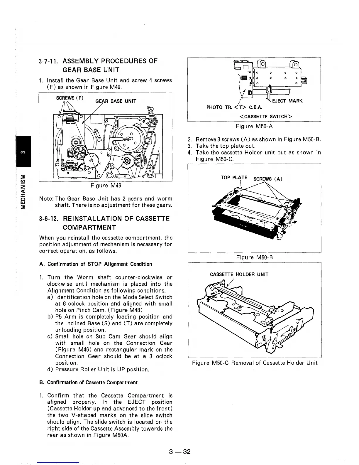
B.
Confirmation of Cassette Compartment
1.
Confirm
that
the Cassette Compartment
is
aligned properly. In the EJECT position
(Cassette Holder up and advanced
to
the
front)
the
two
V-shaped
marks
on
the slide switch
should align. The slide switch
is
located
on
the
right
side
of
the Cassette Assembly
towards
the
rear
as shown
in
Figure M50A.
PHOTO
TR.
<T>
C.B.A.
<
CASSETTE
SWITCH>
Figure M50-A
2.
Remove 3 screws
(A)
as shown
in
Figure M50-B.
3.
Take the
top
plate out.
4.
Take the cassette Holder unit out
as
shown in
Figure M50-C.
Figure M50-B
CASSETTE
HOLDER UNIT
Figure M50-C Removal
of
Cassette Holder
Unit
3-32