>-
...J
cc
~
w
Cl)
Cl)
«
Cl)
Cl
2-2-6 Removal
of
the Rear Panel
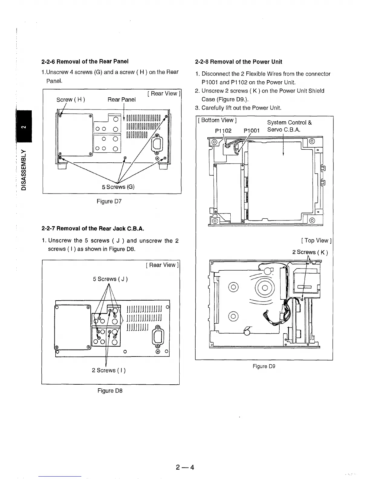
1.Unscrew 4 screws (G) and a screw ( H ) on the Rear
Panel.
[Rear
View 1
Screw ( H ) Rear Panel
®~
loo
01
I~--~®
lo~
~l
5 Screws
(G)
Figure
07
2-2-7 Removal of the Rear Jack C,B,A,
1.
Unscrew the 5
screws
( J ) and
unscrew
the 2
screws (
I ) as shown
in
Figure
08.
[Rear
View 1
o
5 Screws
(J
)
IIJJJJJJJJJJJ1JJ 0
JJJJJJJJJlllJJll
®
®I'---~
JJJJJJJJJJ
0
~---------------=
0 ® 0
2 Screws ( I )
Figure
08
2-4
2-2-8 Removal of the Power Unit
1.
Disconnect the 2 Flexible Wires from the connector
P1001 and P1102
on
the Power Unit.
2. Unscrew 2 screws ( K )
on
the Power Unit Shield
Case (Figure 09.).
3.
Carefully lift out the Power Unit.
[ Bottom View
1
P1102
System Control &
Servo
C.BA
Figure
D9
[Top
View 1
2 Screws
(K)



 To Next Page