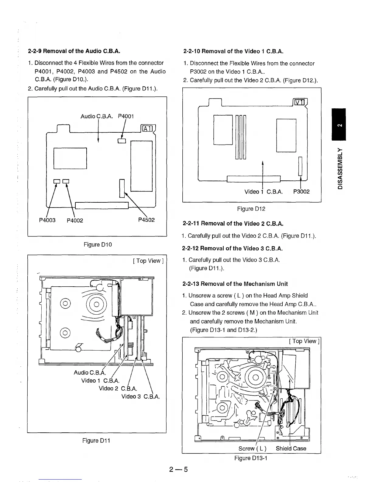
2-2-9 Removal
of
the
Audio
C.B.A.
1.
Disconnect the 4 Flexible Wires from the connector
P4001, P4002, P4003 and P4502 on the Audio
C.B.A. (Figure 010.).
2.
Carefully pull out the Audio C.B.A. (Figure 011.).
Audio C.B.A.
P4001
D
P4003
P4002
P4502
Figure
010
[Top
View 1
Audio C.B.A.
Video 1 C.B.A.
Video 3 C.B.A.
Figure
011
2-2-10 Removal
of
the Video 1 C.B.A.
1.
Disconnect the Flexible Wires from the connector
P3002
on
the Video 1 C.B.A
..
2.
Carefully pull out the Video 2 C.B.A. (Figure 012.).
D
D
Video 1 C.B.A. P3002
Figure
012
2-2-11
Removal
of
the
Video 2 C.B.A.
1.
Carefully pull out the Video 2 C.B.A. (Figure 011.).
2-2-12 Removal
of
the
Video 3 C.B.A.
1.
Carefully pull out the Video 3 C.B.A.
(Figure
011.).
2-2-13 Removal
of
the
Mechanism Unit
1.
Unscrew a screw ( L ) on the Head Amp Shield
Case and carefully remove the Head Amp C.B.A
..
2.
Unscrew the 2 screws ( M ) on the Mechanism Unit
and carefully remove the Mechanism Unit.
(Figure
013-1 and 013-2.)
[Top
View]
Screw ( L ) Shield Case
Figure 013-1
2-5
>-
...J
DJ
~
w
en
en
«
en
Cl