i:l!!
en
z
«
:c
u
w
:l!!
3-5-7. REPLACEMENT OF THE
INCLINED BASE (S),(T)
Supply
Side
1.
Unscrew a screw (I) and remove the head
cleaning plate unit
as
shown in Figure M16-A.
2.
Unscrew the 2 screws (J) and remove the post
stopper.
CUT WASHER
DD CYLINDER
HEAD
CLEANING
PLATE
UNIT
Figure M16-A
3.
Remove the
P2
post unit from loading arm (5)
as
shown
in
Figure M 16-B.
SECTOR
GEAR
P2
POST
UNIT
o
LOADING GEAR
(T)
LOADING GEAR
(s)
Figure M16-B
4.
Pull out the Inclined base (5) from loading base.
5.
The new inclined base unit can be reinstalled by
reversing the removal procedure.
Note:
Install post stopper pusing the arrow direction
(A),(B)
as
shown
in
Figure M16-A.
After re-installing the inclined base
(5)
confirmation of tape interchangeability and
P2,
P3 posts adjustments are required.
Take-up
Side
1.
Unscrew a screw
(K)
and remove the inclined
base (T)
as
show
in
Figure M14.
Figure M16-C
2.
Install the inclined base (T) so that the tip of
inclined base
is
center
on
the Plate Hole and then
tighten screw (K).
Note: After re-installing the inclined base
(T)
confirmation of tape interchangeability and
inclined base adjustment are required.
3-5-8. REPLACEMENT OF THE
P5
POST
1.
Remove the top cover
and
cassette holder.
2.
Rotate the loading motor to clockwise, until the
stop mode.
3.
Remove the pressure roller unit.
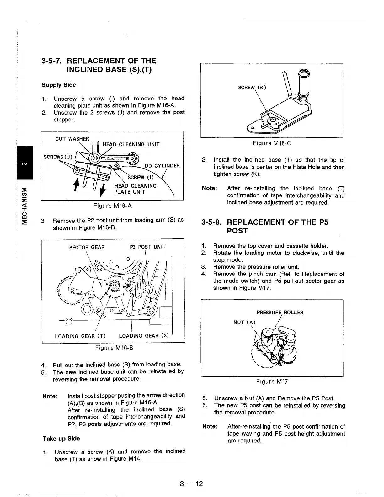
4.
Remove the pinch cam (Ref. to Replacement of
the mode switch) and
PS
pull out sector gear
as
shown
in
Figure M17.
PRESSURE
ROLLER
Figure
M17
5.
Unscrew a Nut
(A)
and Remove the
PS
Post.
6.
The new
PS
post can be reinstalled by reversing
the removal procedure.
Note: After-reinstalling the
PS
post confirmation of
tape waving and
PS
post height adjustment
are required.
3-12