en
I-
Z
W
i
:2
t-
en
I ::J
...,
Cl
«
...J
C3
CC
l-
Q
w
...J
w
4-1. TEST & SERVICE
EQUIPMENT
To perform the electrical adjustment completely the
following equipments are required.
1.
VTVM (Vacuum Tube Volt Meter)
Capacity :
0.001
to 50V
2.
DVM
(Digital Volt Meter)
Capacity :
0.001
to 50V
3. Dual-Trace Oscilloscope (with probes)
Capacity :
0.005 to 50V/div,
DC
to 30MHz
4.
Frequency Counter
Capacity :
0 to 10MHz
5.
Sine Wave Signal Generator
(RC
Oscilfator)
Capacity :
0 to 10MHz
6.
Video Signal Generator (Composite)
7.
Spectrum analyzer
8.
Color Monitor TV
9.
Waveform Monitor
10. Alignment Tape (VFM8080HQFP)
4-2. HOW TO READ THE
ADJUSTMENT PROCEDURE
TABLE
BOARD
TP
ADJ
TAPE
INPUT
MODE
M.EQ
SPEC
BOARD:
TP:
ADJ.:
TAPE:
INPUT:
MODE:
M.EQ:
SPEC:
MAIN C.B.A.
TP3502
[F-2]
VR2002
rA-3]
ALIGNMENT
TAPE
COLOUR
BAR
PLAY
OSCILLOSCOPE
T = 8.5 ±
O.5H
Adjustment position of Print Circuit Board.
Connection point (Test
Point) of
measuring eqUipment
* ( ) shown TP location
on
the board.
Adjustment component
* ( ) shown
VR
location
on
the board.
Tape for adjustment.
Supply a signal for adjustment.
Mode of VTR.
Example:
REC
->
PLAY
is
recording
signal and playback the
portion just recorded.
Measuring equipment.
Specification for adjustment.
4-3. ELECTRICAL ADJUSTMENT
PROCEDURES
4-3-1.
PG
SHIFTER ADJ.
BOARD
SERVO
&
SYSTEM
CONTROL
C.B.A.
TP
TP8002LHEAD SW)(A-1),
VIDEO
OUT
ADJ
VR2002(A-4)
TAPE
VFM8180HADH
PORTION: 2
INPUT
MODE
PLAY
M.EQ
OSCILLOSCOPE
SPEC
T =
8.5
±
O.5H
Note: This adjustment should
be
performed only
after completion of the Tape Interchangeability
adjustment.
1.
Playback the alignment tape at the portion
2.
2.
Connect the oscilloscope to TP8002 for
CH1
and
Video
Out for CH2.
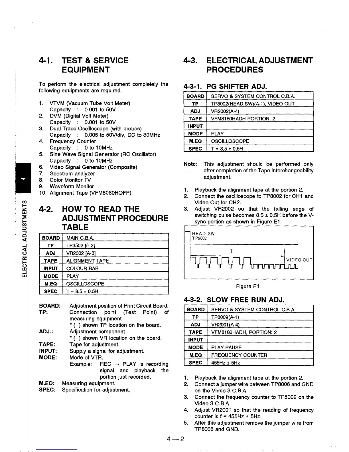
3.
Adjust VR2002 so that the falling edge of
switching pulse becomes 8.5
±
O.5H
before the V-
sync portion
as
shown
in
Figure
E1.
l HEAD
SW
TP8002
hurvmnrnnmkO
OUT
Figure
E1
4-3-2. SLOW FREE
RUN
ADJ.
BOARD
SERVO
&
SYSTEM
CONTROL
C.B.A.
TP
TP8009(A-1 )
ADJ
VR2001 (A-4)
TAPE
VFM8180HADH,
PORTION: 2
INPUT
MODE
PLAY
PAUSE
M.EQ
FREQUENCY
COUNTER
SPEC
455Hz
±
5Hz
1.
Playback the alignment tape at the portion
2.
2.
Connect a jumper wire between TP8006 and GND
on
the Video.3
C.BA
3.
Connect the frequency counter to TP8009
on
the
Video 3 C.B.A.
4.
Adjust VR2001 so that the reading of frequency
counter
is
f = 455Hz ± 5Hz.
5. After this adjustment remove the jumper wire from
TP8006 and GND.
4-2