:2!
Cl)
z
«
:::I:
()
w
:E
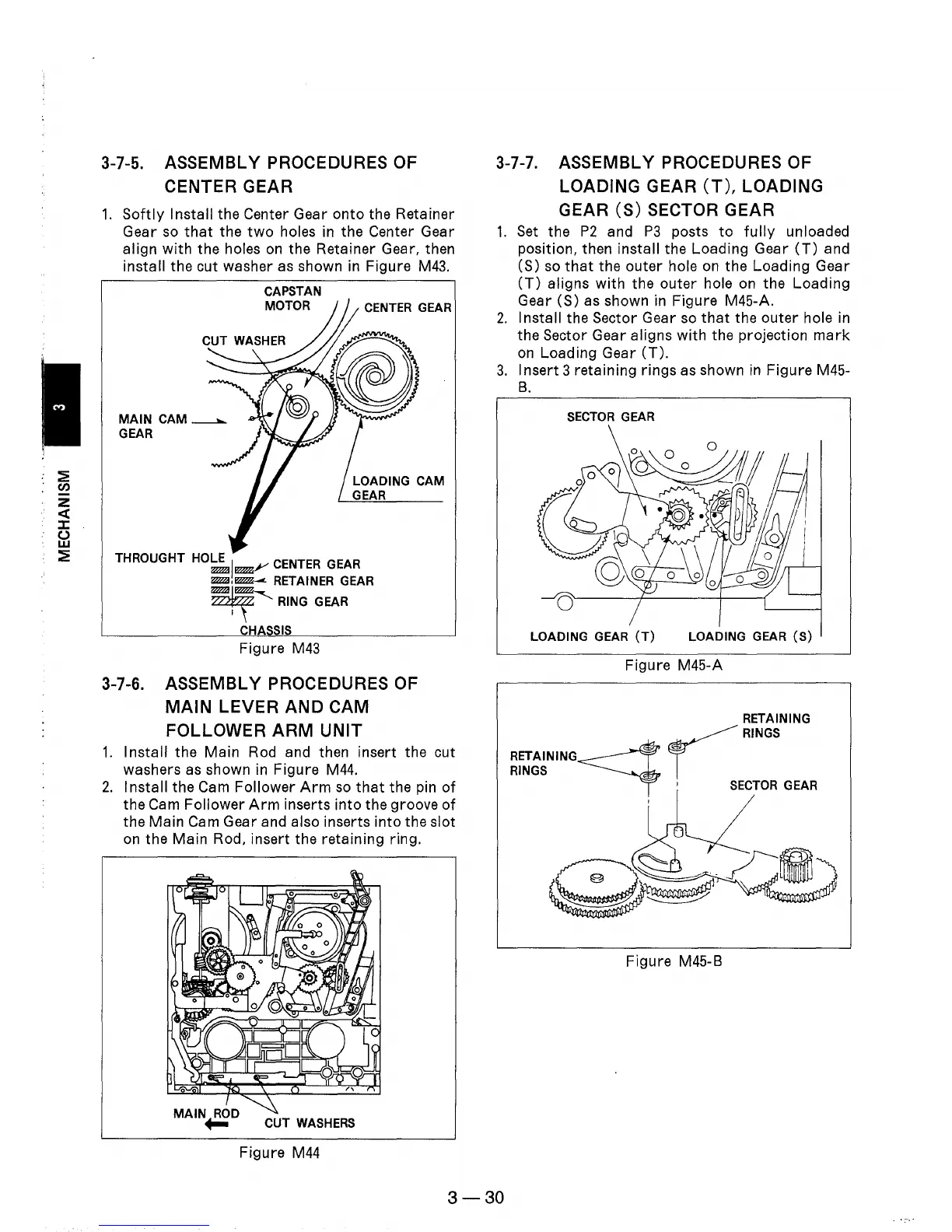
3-7-5. ASSEMBLY PROCEDURES OF
CENTER
GEAR
1.
Softly
Install the Center Gear onto the Retainer
Gear
so
that
the
two
holes
in
the Center Gear
align
with
the holes
on
the Retainer Gear, then
install the cut washer
as
shown in Figure
M43.
CAPSTAN
MOTOR
CENTER GEAR
LOADING CAM
GEAR
THROUGHT
HOLE I CENTER GEAR
WZl
~.r'
WZl,~-
RETAINER GEAR
~RING
GEAR
CHASSIS
Figure
M43
3-7-6. ASSEMBLY PROCEDURES OF
MAIN
LEVER
AND
CAM
FOLLOWER
ARM
UNIT
1.
Install the Main Rod and then insert the cut
washers
as
shown
in
Figure
M44.
2.
Install the
Cam
Follower
Arm
so
that
the pin
of
the
Cam
Follower
Arm
inserts into the groove
of
the Main Cam Gear and also inserts into the slot
on
the Main Rod, insert the retaining ring.
CUT WASHERS
Figure
M44
3-7-7.
ASSEMBLY PROCEDURES OF
LOADING
GEAR
(T),
LOADING
GEAR
(S)
SECTOR GEAR
1.
Set
the
P2
and
P3
posts
to
fully
unloaded
position, then install the Loading Gear
(T)
and
(S)
so
that
the outer hole
on
the Loading Gear
(T)
aligns with the outer hole
on
the Loading
Gear (S) as shown
in
Figure M45-A.
2.
Install the Sector Gear
so
that
the outer hole
in
the Sector Gear aligns with the projection
mark
on
Loading Gear
(T).
3.
Insert 3 retaining rings as shown
in
Figure M45-
B.
SECTOR
GEAR
LOADING GEAR
(T)
LOADING GEAR
(S)
Figure M45-A
RETAINING
r
RINGS
RETAINING~
RINGS
I
SECTOR
GEAR
Figure M45-B
3-30