~
en
,Z
«
J:
()
w
.;2
3-7. ASSEMBLY AND ADJUSTMENT
PROCEDURES
OF MECHANISM
The mechanism
of
this
model
is
mostly engaged
to
the System Control Circuit,
through
the mode
select switch. Therefore the relation between the
mode select switch and the cam gear decides all
further
mechanical movement
of
the mechanical
parts
such as levers, gears, rollers and
so
on.
If
these
parts
are
not
fixed properly, the
unit
will
be
unloaded
or
compulsorily stopped. And
it
will
result being damaged
at
any mechanical
or
electrical parts. The overall mechanical condition
(alignment)
of
bottom
and
top
view are shown
in
Figure
M39-A and Figure M39-B. This mechanical
adjustment is performed
in
the STOP mode.
3-7-1.
CONFIRMATION
OF
ALIGNMENT
CONDITION
1.
Remove the Loading Belt.
2.
Unscrew 4 screws
(F)
and remove the Gear
Base
Unit.
(Figure
M39-A)
3.
Turn
the Center Gear
to
counter-clockwise until
2 big holes
of
Center Gear align with 2 big holes
of
Retainer Gear and Ring Gear and Chassis
as
shown
in
Figure M39-C.
SCREWS
(F)
GEAR
BASE
UNIT
Fiugre M39-A
CENT
ER
GEAR
PINCH
SPEED
---I[h.,.,~""
DOWN GEAR
DETENT ARM
--~
\
4.
Identification hole
on
the Mode Select Switch
at
6 oclock position and aligned with small hole
on
Pinch Cam
as
shown
in
Figure M39-B.
5.
P5
Arm
is completely loading position and the
Inclined
Base
(S) and
(T)
are completely
unloading position.
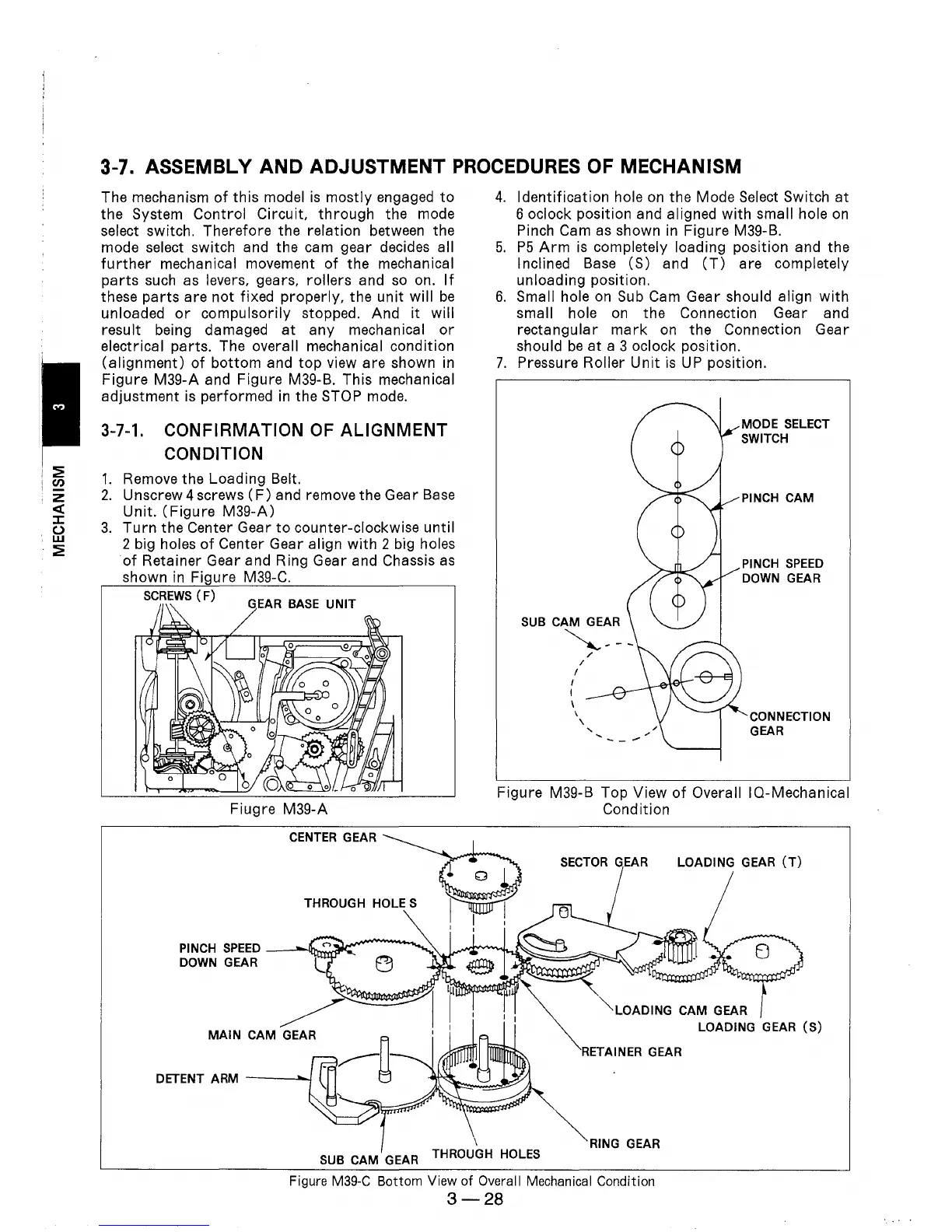
6.
Small hole
on
Sub
Cam Gear should align
with
small hole
on
the Connection Gear and
rectangular
mark
on
the Connection Gear
should
be
at
a 3 oclock position.
7.
Pressure Roller
Unit
is
UP
position.
SUB CAM GEAR
~---
I
I
\
/
I
\
\
/
"
'"
--
..--
PINCH
CAM
PINCH
SPEED
DOWN GEAR
CONNECTION
GEAR
Figure M39-B Top View
of
Overall IQ-Mechanical
Condition
SECTOR
GEAR LOADING GEAR
(T)
"'-LOADING
CAM GEAR
LOADING GEAR
(S)
RETAINER GEAR
~RING
GEAR
SUB CAM GEAR THROUGH HOLES
Figure
M39-C
Bottom View
of
Overall Mechanical Condition
3-28