3-6-12. HEIGHT ADJUSTMENT OF THE
REEL
TABLES
<<TOOL»
Post Adjustment Plate
Reel Table
Height Gauge
VFK0191
VFK0190
«SPEC»
O-O.15mm
1 . Remove the cassette compartment.
2.
Place the post Adjustment Plate
on
the reel tables.
3.
Place the Reel Table Height Gauge
on
the plate
so
that the scraper of the gauge touches the cut-
out portion
of
the plate, then set the gauge to zero
o as shown
in
Figure M35-A.
Figure M35-A
4.
Measure the height of the top surface of either
Reel table and note the difference
in
height from
the
plate cut-out (Figure M35-A and M35-B).
Repeat this procedures for the other
Reel Table.
Figure M35-B
5.
If the difference
of
Supply Reel table
is
more than
O.15mm
higher or lower, replace the Supply Reel
table.
When the difference of Take Up Reel table
is more than
O.15mm
higher or lower, adjust nut
(A)(Figure M35-C) so that measurement becomes
the spec.
If
you
can
not adjust
to
the spec.,
replace Take Up Reel table.
NUT
(A)
r---L----~____,
TAKE-UP
REEL
TABLE
Figure M35-C
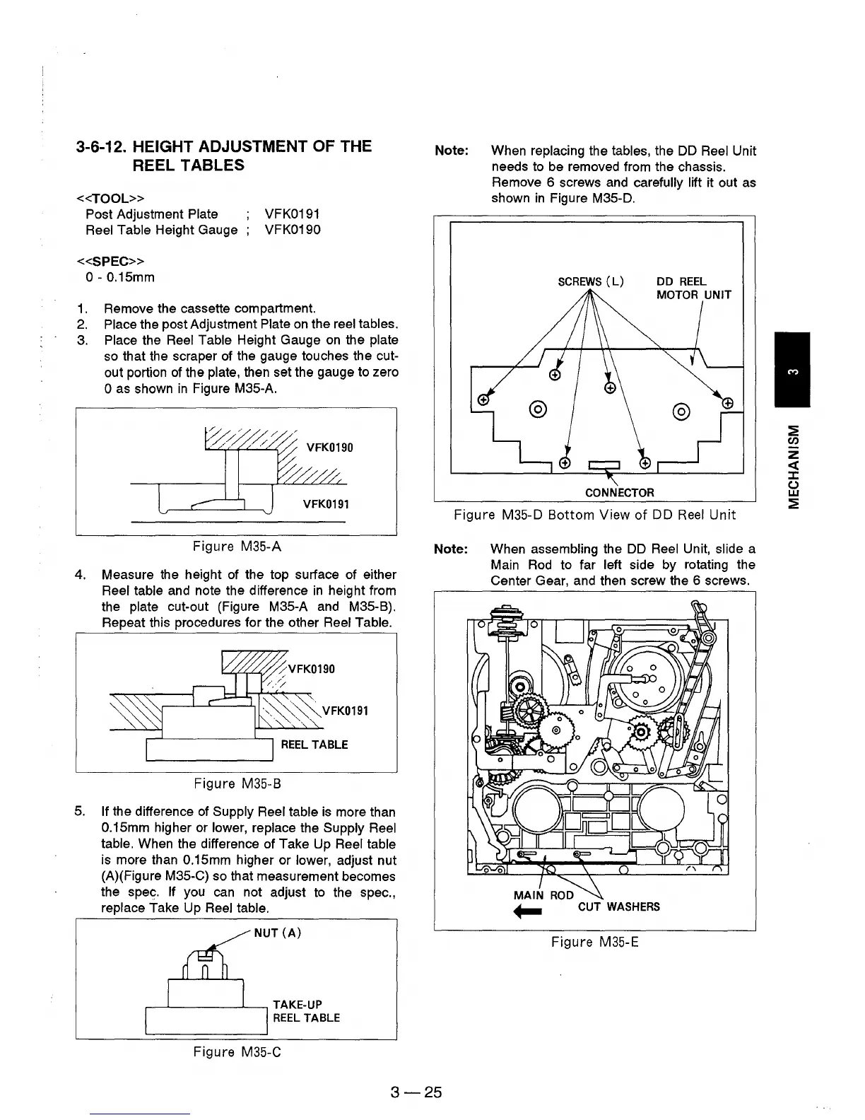
Note: When replacing the tables, the
DD
Reel Unit
needs
to
be removed from the chassis.
Remove 6 screws and
carefully lift it out
as
shown
in
Figure M35-D.
SCREWS
(L)
CONNECTOR
Figure M35-D
Bottom
View
of
DD
Reel
Unit
Note: When assembling the
DD
Reel Unit, slide a
Main
Rod
to far left side by rotating the
Center Gear, and then screw the 6 screws.
MAIN
ROD
~
CUT WASHERS
Figure M35-E
3-25
:2
(/')
z
«
J:
()
w
:2