(IJ
I-
Z
w
~
I-
(IJ
::J
-,
Cl
«
..J
«
()
a:
I-
()
w
..J
W
4-3-7.
CNR
ADJ.
BOARD
VIDEO
1 C.B.A.
TP
T3804(A-1)
ADJ
VR3803(A-1), VR3806(A-1)
TAPE
S-VHS SELF RECORDED TAPE
INPUT COLOUR BAR SIGNAL
MODE PLAY
M.EQ OSCILLOSCOPE
SPEC C
LEVEL = MINIMUM
Note: This adjustment should
be
always completed
after 4-3-6.
DOC
BALANCE adj.
[SET UP]
S-VHS SW =
ON
1.
Record the colour bar signal a few minutes by the
S-VHS mode.
.
2.
Connect the oscilloscope to TP3804.
3.
Playback the just recorded portion.
4.
Adjust VR3803 and VR3806 mutually so that
chroma signal becomes minimum
as
possible.
TP3804
(H.RATE)
MINIMUM
Figure
E3
4-3-8. CHARACTER POSITION ADJ.
BOARD VIDEO 2 C.B.A.
TP
VIDEO OUT
ADJ
C3111 (B-1)
TAPE
INPUT COLOUR BAR SIGNAL
MODE
E-E
M.EQ
MONITOR
SPEC SEE FIGURE
1.
Supply a colour bar signal to the video input.
2.
Set the MENU Switch to SET.
The menu screen appears
on
the monitor TV. (If
the Hour Meter
is
appeared, advance to the next
page by using the PLAY
(-)
or
REC
(+) button.)
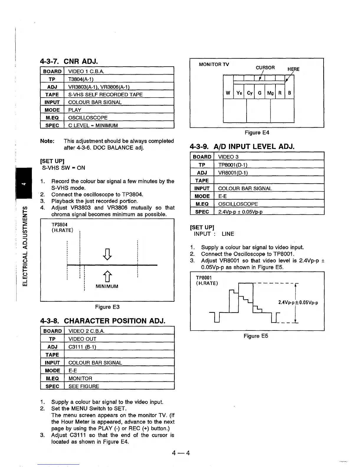
3.
Adjust
C3111
so that the end of the cursor
is
located
as
shown
in
Figure
E4.
4-4
MONITOR
TV
CURSOR
Figure E4
4-3-9. AID INPUT LEVEL ADJ.
BOARD VIDEO 3
TP
TP8001(D-11
ADJ
VR8001
(D-1
)
TAPE
INPUT COLOUR BAR SIGNAL
MODE
E-E
M.EQ
OSCILLOSCOPE
SPEC
2.4Vp-p + O.05Vp-p
[SET UP]
INPUT:
LINE
1.
Supply a colour bar signal to video input.
2.
Connect the Oscilloscope to TP8001.
3.
Adjust VR8001 so that video level is 2.4Vp-p ±
O.05Vp-p
as
shown
in
Figure
E5.
TP8001
(H.RATE)
Figure
E5