Names and Functions of Parts
2.1 Analog Input Unit (FP0R-AD4/AD8)
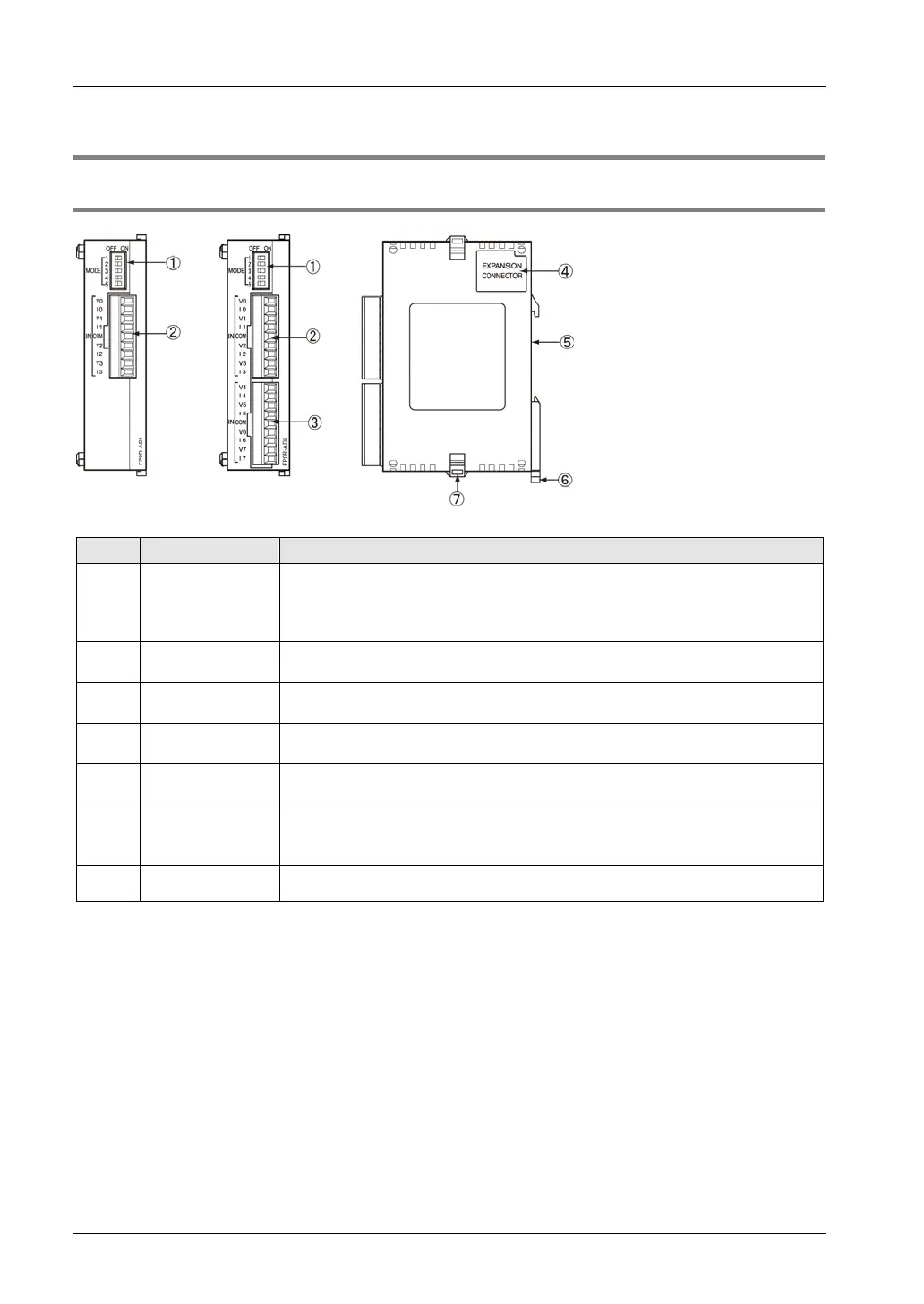
2.1.1 Names and Functions of Parts
Names and Functions of Parts
①
Mode setting
switch
Used for selecting the input range, the number of input channels and whether
to use the averaging processing or not.
Used for selecting the operation mode (12-bit mode or 14-bit mode compatible
with the conventional product FP0-A80).
②
Input terminal
for CH0-CH3
Used for connecting the analog input device.
③
Input terminal
for CH4-CH7
Used for connecting the analog input device.
④
Expansion
connector
Used for connecting the expansion unit with the internal circuit of the Control Unit.
⑤
DIN rail installing
groove
It can be installed to a 35-mm-wide DIN rail.
⑥
DIN hook
The unit can be installed to the DIN rail through one-touch operation.
This hook is also used for installing the unit to the Slim Type Mounting Plate
(AFP0803).
⑦
Expansion hook Used for securing expansion units.

 Loading...


