4.3 Analog Output Unit (FP0R-DA4)
4-23
4.3.5 Status information (14-bit mode)
With the analog output unit, the following information can be monitored in the external input
area WX.
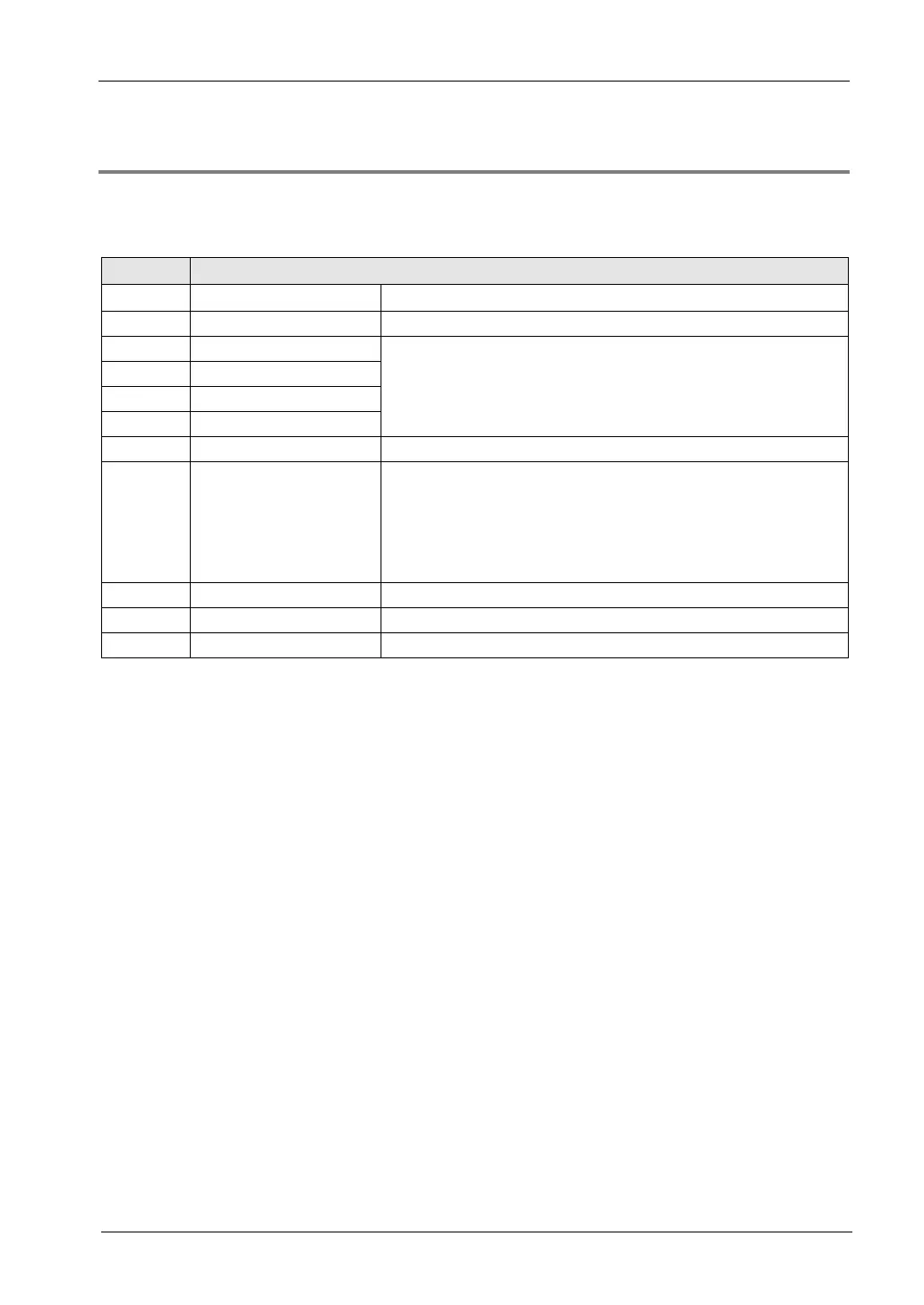
Status information
X20 Analog output unit power
0:OFF, 1:ON、
X21-X23 Used in the system
X24 CH0 data writing status
0:Normal, 1:Error (Note 1)
An error occurs when data written to the memory area (WY2/WY3) is
out of each range, and the data conversion is not performed. The
error is cleared when data within the range is written and the
conversion is performed.
X25 CH1 data writing status
X26 CH2 data writing status
X27 CH3 data writing status
X28-X2F Used in the system
X30-X33 CH0 range setting state
The state of a specified output range can be monitored. The following
constants are stored for each range.
H0: -10V to +10V, 0mA to 20mA
H1: -5V to +5V,4mA to 20mA
H2: 0V to 10V
H3: 0V to 5V
X34-X37 CH1 range setting state Same as above.
X38-X3B CH2 range setting state Same as above.
X3C-X3F CH3 range setting state Same as above.
(Note 1):As output data and the output switching flag are allocated to the same I/O, a data error is detected correctly
only when a digital input value is within (K-8192 to K8191) for the ±range and (K0 to K16383) for the + range. In
the case of digital input values exceeding these ranges, data may be converted without an error, so always
insert a program which checks the upper and lower limits.
(Note 2):In the 14-bit mode, the range setting state of each channel specified in WY2 and WY3 can be confirmed.

 Loading...


