2.2 Analog Output Unit (FP0R-DA4)
2-5
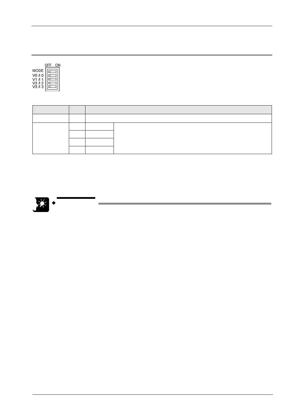
2.2.2 Setting of Mode Switch
Setting of the mode switch
Resolution 1
OFF:FP0-A04V/A04I compatible 12-bit mode, ON:14-bit mode (Note 1)
Output switch
2 CH0
OFF:Voltage output
ON:Current output (Note 2)
3 CH1
4 CH2
5 CH3
(Note 1): In the 14-bit mode, the output range is set by writing into the operation memory WY with a user program.
(Note 2): For the both FP0-A04V/A04I compatibility 12-bit mode and 14-bit mode, the output can be selected for each
channel.
(Note 3): All the switches are set to OFF at the factory.
(Note 4): The switch settings will be valid when the power is turned ON from OFF. The settings will not change if the
operation power supply is switched when it is ON.
• In the FP0-A04V/A04I compatibility 12-bit mode, the voltage output range is
-10 to +10 V, and the current output range is 4 to 20 mA.

 Loading...


