Creating Programs
4.4.3 Writing of Digital Data for Output (12-bit Mode)
The analog I/O unit (FP0R-A42/A21) writes data for conversion as the output switching flags
are not contained in the 12-bit mode.
I/O allocation (12-bit mode)
WY3 WY2
CH1 data CH0 data
Writing data for conversion
• The analog I/O unit writes the analog output digital data of a maximum of 2 channels to two
memory areas (WY2/WY3) by user programs.
• Always insert a program which checks the upper and lower limits to make
written digital values be within the allowable data ranges referring the
programs described on the following pages.
12-bit mode
± range -2000
+ range 0
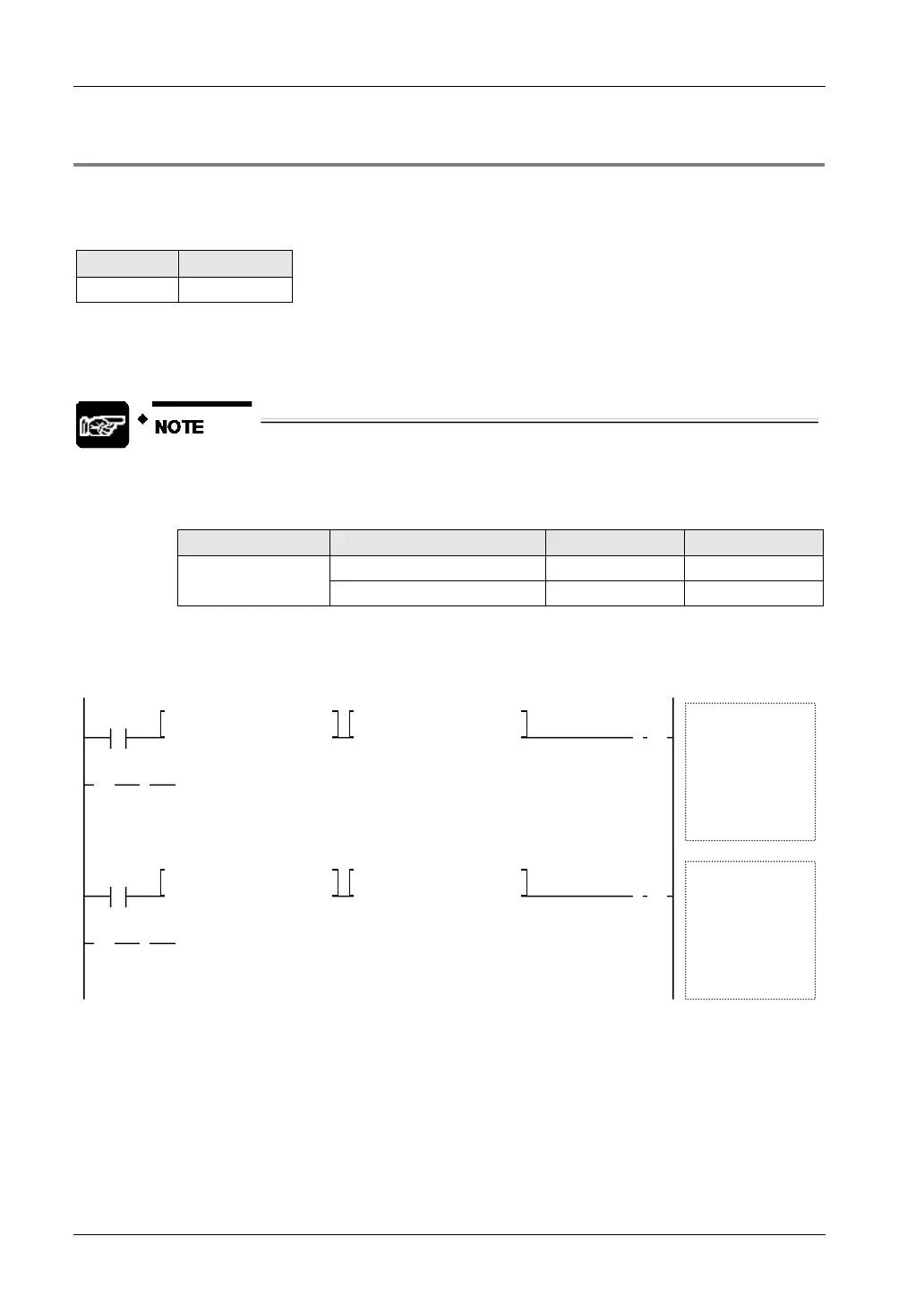
Sample program (12-bit mode: -10V to +10V range)
The following program shows the case that the data of DT0 to DT1 is converted and output to
the CH0 to CH1 of the first expansion analog I/O unit (FP0R-A42/A21).
<= K-2000 , DT0
R9010
[ F0 MV , DT0 , WY2
]
1
>
1
>
>= K 2000 , DT0
①
④ ⑤
② ③
ⓐ
CH0
<= K-2000 , DT1
R9010
[ F0 MV , DT1 , WY3 ]
1
>
1
>
>= K 2000 , DT1
①
④ ⑤
② ③
ⓑ
CH1

 Loading...


