6.1 Table of Specifications
6-3
6.1.2 Input Specifications
Item
Input range
(Resolution)
Voltage
-10 to 10 V DC (Resolution:1/16,000) (Note 1)
-5 to 5 V DC (Resolution:1/16,000)
0 to 10 V DC (Resolution:1/16,000)
0 to 5 V DC (Resolution:1/16,000)
-100 to 100 mV DC
(Resolution:1/4,000) (Note 4)
-
0 to 20 mA (Resolution:1/16,000) (Note1)
Digital input
range
(Note 2)
K -2000 to K2000 (12-bit mode)/ K-8000 to K8000 (14-bit mode)
K-8000 to K8000 (14-bit mode only)
K0 to K16000 (14-bit mode only)
-100 to 100 mV DC
(Note 4)
K -2000 to K2000 (12-bit mode only) -
K0 to K4000 (14-bit mode)/ K0 to K16000 (14-bit mode)
2 ms / All channels (Note 3)
Overall
precision
±0.6%F.S. or less (at 25°C)
±1.0%F.S. or less (at 0 to +55°C)
-
Others ±0.2%F.S. or less (at 25°C) ±0.4%F.S. or less (at 0 to +55°C)
Current ±0.3%F.S. or less (at 25°C) ±0.6%F.S. or less (at 0 to +55°C)
maximum
-15 to 15 V (Voltage input)
Current -30 to 30 mA (Current input)
Insulation
method
terminal to
Photocoupler
Insulation-type DC/DC converter
Uninsulated
Switched to the 12-bit operation by the dip switch.
External connection method
Connection terminal block connection
(Note 1):The resolution in the 12-bit mode is 1/4,000.
(Note 2): In the analog input unit Ver.1.1 or older or the analog I/O unit, a digital conversion value equivalent to the
analog input of approx. 2 V is saved in the device (WX), for the channels to which no input is connected. The
analog input unit Ver.1.2 or after are equivalent to approx. 0 V.
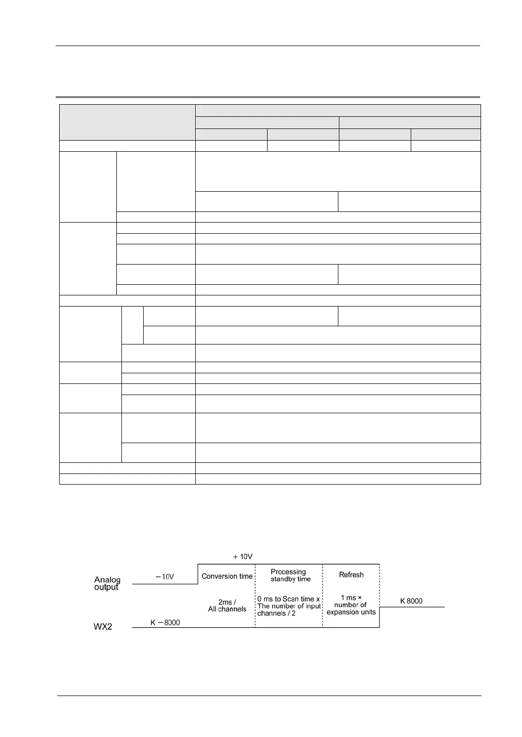
(Note 3): The time shown in the figure below is required to reflect analog input values in the input device area (WX)
read by the control unit. The following figure shows the values when the range of -10 to +10 V is used.
(Note 4): Installed in the unit of Ver.1.2 and after (only 12-bit mode)

 Loading...


