Specifications
6.1.3 Output Specifications
Item
Description
Analog output unit Analog I/O unit
Number of outputs 4 ch 1 ch 2 ch
Output
range
(Resolution
Voltage
-10 to 10 V DC (Resolution:1/16,000) (Note 1)
-5 to 5 V DC (Resolution:1/16,000)
0 to 10 V DC (Resolution:1/16,000)
0 to 5 V DC (Resolution:1/16,000)
Current
0 to 20 mA (Resolution:1/16,000) (Note1)
4 to 20 mA (Resolution:1/16,000) (Note1)
Digital
output
range
-10 to 10 V DC
K-2000 to K2000 (12-bit mode)/ K-8000 to K8000 (14-bit mode)
-5 to 5 V DC K-8000 to K8000 (14-bit mode only)
0 to 10 V DC
0 to 5 V DC
K0 to K16000 (14-bit mode only)
0 to 20 mA
4 to 20 mA
K0 to K4000 (12-bit mode)/ K0 ~ K16000 (14-bit mode) (Note1)
Conversion speed
500 µs / All channels (Note 2)
Overall
precision
Voltage
±0.2%F.S. or less (at 25°C) ±0.4%F.S. or less (at 0 to +55°C)
Current ±0.3%F.S. or less (at 25°C) ±0.6%F.S. or less (at 0 to +55°C)
Output impedance 0.5 Ω or less (Voltage output)
Maximum outputcurrent ±10 mA (Voltage output)
Allowable outputload resistance 600 Ω or less (Current output)
Insulation
method
Between input
terminal to
internal circuit
Photocoupler
Insulation-type DC/DC converter
Between the
channels
Uninsulated
External connection method Connection terminal block connection
(Note 1):The resolution in the 12-bit mode is 1/4,000. Also, the output current range in the 12-bit mode is 4 to 20 mA
for AFP0RDA4, and 0 to 20 mA for AFP0RA21/AFP0RA42.
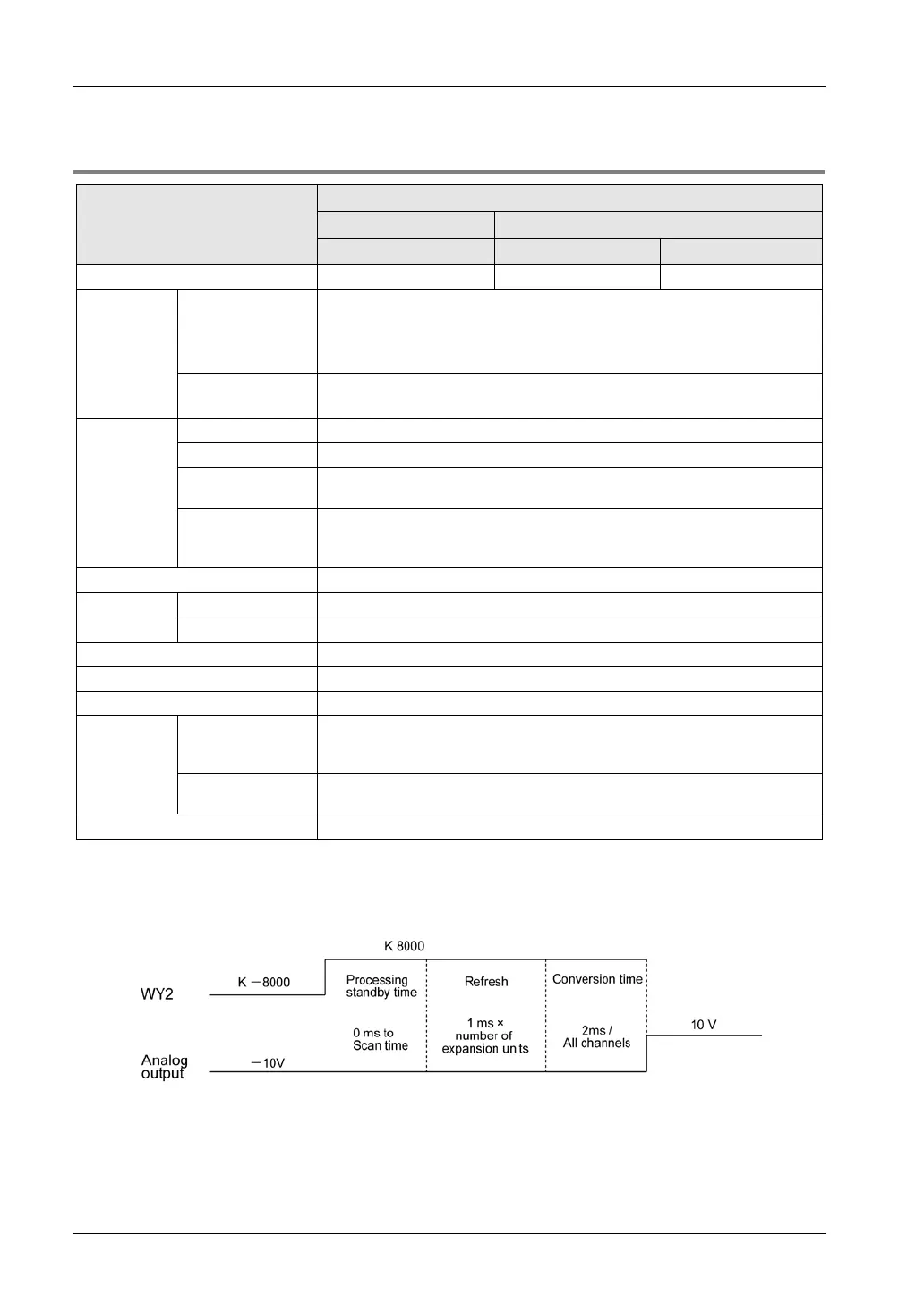
(Note 2): The time shown in the figure below is required to reflect the values in the output device area (WY) of the
control unit as analog output values. The following figure shows the values when the range of -10 to +10V is
used.
Precautions on the characteristics of analog output
When the power to the control unit turns on or off, voltage (equivalent to 2 V) may be output for approx. 2 ms from
the output terminal. If it will be a problem on your system, take necessary measures externally to avoid the
transitional condition, e.g. turning on PLC before external devices or turning off external devices before PLC.

 Loading...


