Creating Programs
4.4.4 Writing of Digital Data for Output (14-bit Mode)
With the analog I/O unit (FP0R-A42/A21), the conversion output is performed by using two
bits as the switching flags of output channels and writing data.
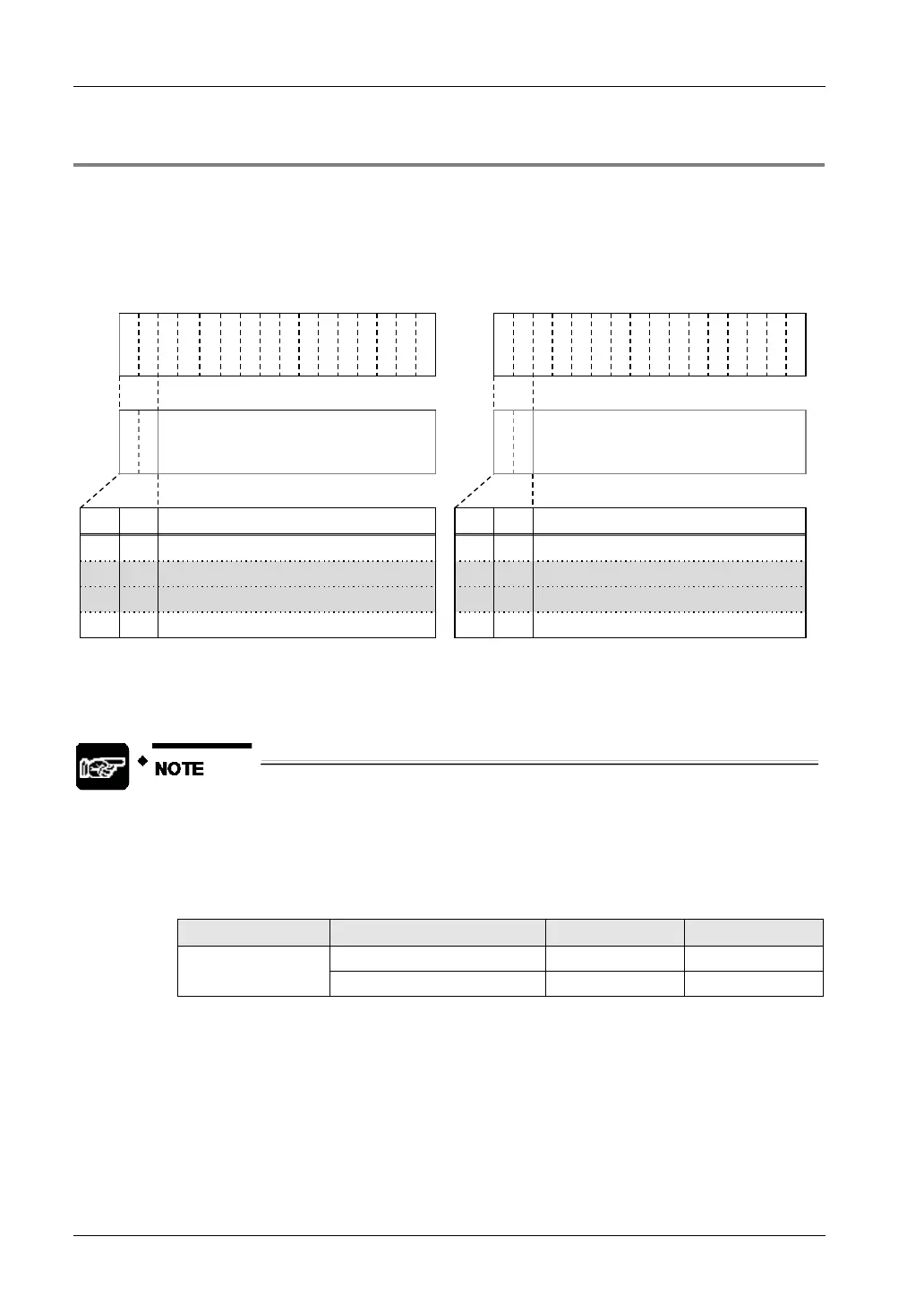
I/O allocation (14-bit mode)
In the 14-bit mode, the most significant two bits are used as the switching flags. They are
common to the flags for setting ranges.
Y
3
F
Y
3
E
Y
3
D
Y
3
C
Y
3
B
Y
3
A
Y
3
9
Y
3
8
Y
3
7
Y
3
6
Y
3
5
Y
3
4
Y
3
3
Y
3
2
Y
3
1
Y
3
0
Y
2
F
Y
2
E
Y
2
D
Y
2
C
Y
2
B
Y
2
A
Y
2
9
Y
2
8
Y
2
7
Y
2
6
Y
2
5
Y
2
4
Y
2
3
Y
2
2
Y
2
1
Y
2
0
A
1
A
0
Output data of CH1 (14bit)
Input average setting: CH0
-CH3
CH1 output range setting
A
1
A
0
Output data of CH0 (14bit)
Input average setting: CH0
-CH3
CH0 output range setting
A1 A0
Item
A1 A0 Item
0 0 CH1 output data setting 0 0 CH0 output data setting
0 1
Input average setting 0 1 Input range setting
1 0
CH1 output range setting
1 0 CH0 output range setting
1 1 CH1 output data setting 1 1 CH0 output data setting
Writing data for conversion
• The analog I/O unit writes the analog output digital data of a maximum of 2 channels to two
memory areas (WY2/WY3) by user programs.
• Protect output switching flags from being overwritten by a subsequent
program after writing data. Output data becomes invalid.
• Always insert a program which checks the upper and lower limits to make
written digital values be within the allowable data ranges referring the
programs described on the following pages.
14-bit mode
±range -8000
+range 0
• For the analog I/O unit (FP0R-A21/A42), the data setting becomes valid
when the output switching flags (Y2F, Y2E) or (Y3F, Y3E) are (0, 0) or (1, 1).
When written digital values are within the range in the above table, it is not
necessary to add programs for setting or setting the output switching flags
after data transmission like the following programs because the output
switching flags (Y2F, Y2E) or (Y3F, Y3E) are always (0, 0) or (1, 1).

 Loading...


