Creating Programs
4.4 Analog I/O Unit (FP0R-A21/A42)
4.4.1 Reading of Analog Input Values (For A21)
With the analog input unit A21, data can be read as signed 16-bit data as is.
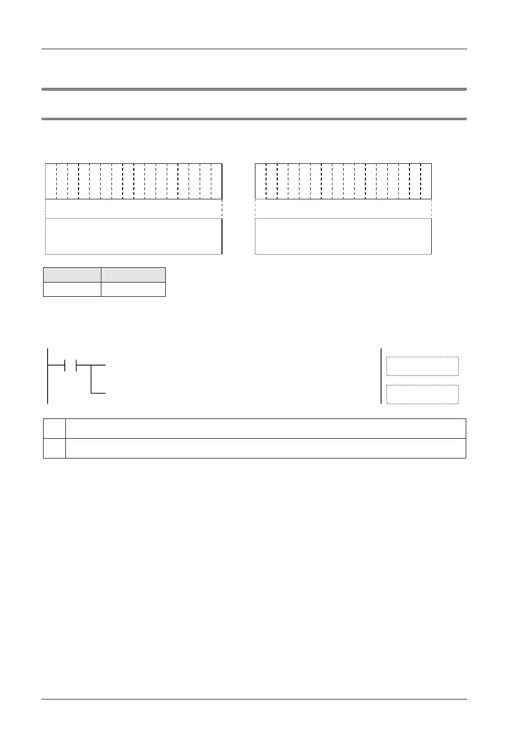
I/O allocation (External input WX)
X
3
F
X
3
E
X
3
D
X
3
C
X
3
B
X
3
A
X
3
9
X
3
8
X
3
7
X
3
6
X
3
5
X
3
4
X
3
3
X
3
2
X
3
1
X
3
0
X
2
F
X
2
E
X
2
D
X
2
C
X
2
B
X
2
A
X
2
9
X
2
8
X
2
7
X
2
6
X
2
5
X
2
4
X
2
3
X
2
2
X
2
1
X
2
0
Conversion data of CH1
(16 bit with sign)
Conversion data of CH0
(16 bit with sign)
CH1data CH0 data
Sample program (For FP0R-A21)
The following program shows the case that conversion data of the first expansion analog input
unit (FP0R-A21) (CH0 to CH7) is read and stored in DT0 to DT7.
[ F0 MV , WX3 , DT1 ]
[ F0 MV , WX2 , DT0 ]
R9010
ⓐ
ⓑ
ⓐ
The conversion data of CH0 is stored into DT0.
ⓑ
The conversion data of CH1 is stored into DT1.

 Loading...


