Creating Programs
4.3.3 Switching of Output Range (14-bit Mode Only)
When selecting the 14-bit mode in the analog output unit (FP0R-DA4), the output range can
be switched by user programs. It can be set for each channel.
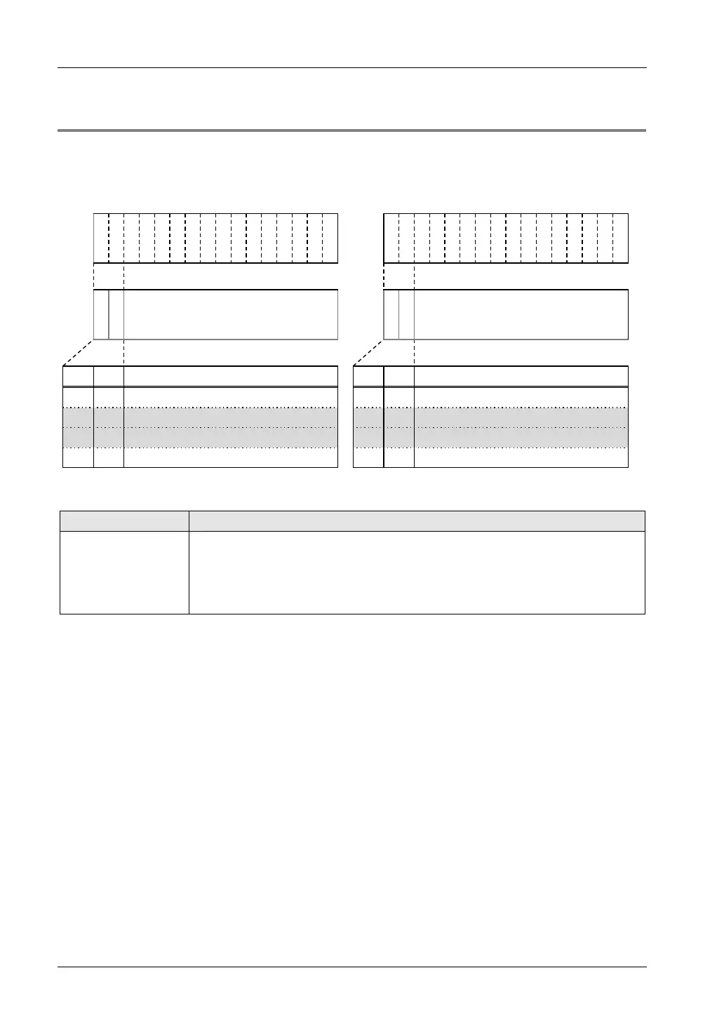
I/O allocation (External input WY)
Y
3
F
Y
3
E
Y
3
D
Y
3
C
Y
3
B
Y
3
A
Y
3
9
Y
3
8
Y
3
7
Y
3
6
Y
3
5
Y
3
4
Y
3
3
Y
3
2
Y
3
1
Y
3
0
Y
2
F
Y
2
E
Y
2
D
Y
2
C
Y
2
B
Y
2
A
Y
2
9
Y
2
8
Y
2
7
Y
2
6
Y
2
5
Y
2
4
Y
2
3
Y
2
2
Y
2
1
Y
2
0
A
1
A
0
Output data of CH1/CH3 (14bit)
Range setting
A
1
A
0
Output data of CH0/CH2 (14bit)
Range setting
A1 A0 Item A1 A0 Item
0 0 CH1 output range setting 0 0 CH0 output range setting
0 1
CH1 output data
0
1 CH0 output data
1 0 CH3 output data 1 0 CH2 output data
1 1 CH3 output range setting 1 1 CH2 output range setting
Each output range is specified by setting the following constants.
Item Description
Output range setting
Input constants for specifying output ranges in the 14-bit area.
H30 -10 to +10V / 0 to 20mA
H31 -5 to +5V / 4 to 20mA
H32 0 to 10V
H33 0 to 5V
Default settings
The default settings are as follows; Output range for all channels: Voltage output range: -10 to
+10 V, Current output range: 0 to 20 mA.

 Loading...


