EasyManuals Logo

Panasonic FP0R Series User Manual

Panasonic FP0R Series
92 pages
To Next Page IconTo Next Page
To Previous Page IconTo Previous Page
Page #20 background imageLoading...
Page #20 background image
Wiring
3-4
3.2 Analog Output Unit (FP0R-DA4)
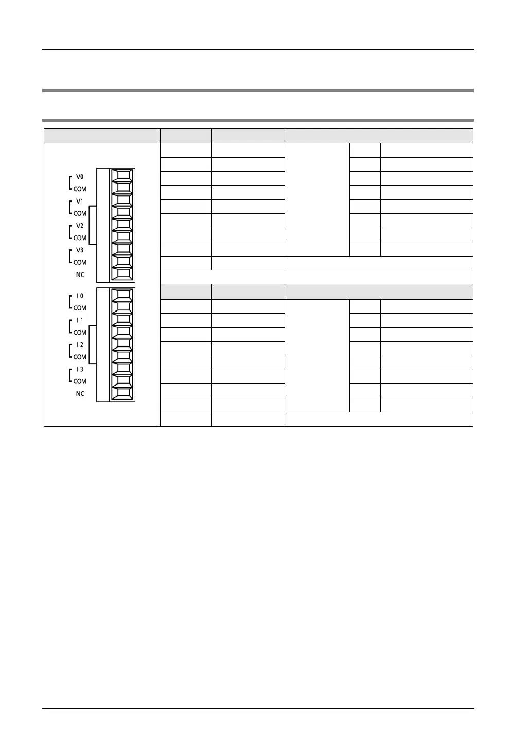
3.2.1 Terminal Layout Diagrams
Appearance
Pin No.
Name
Function
1 V0
Analog output
CH0 Voltage signal output
2 COM ---
Output common
3 VI CH1
Voltage signal output
4 COM --- Output common
5 V2 CH2 Voltage signal output
6 COM --- Output common
7 V3 CH3 Voltage signal output
8 COM ---
Output common
9 NC
Unused
Pin No.
Name
Function
1 I0
Analog output
CH0
Current signal output
2 COM --- Output common
3 I1 CH1 Current signal output
4
COM
---
Output common
5 I2 CH2 Current signal output
6 COM ---
Output common
7 I3 CH3
Current signal output
8 COM --- Output common
9 NC Unused
(Note): All COM terminals are connected within the unit.

Table of Contents

Questions and Answers:

Question and Answer IconNeed help?

Do you have a question about the Panasonic FP0R Series and is the answer not in the manual?

Panasonic FP0R Series Specifications

General IconGeneral
ModelFP0R Series
ExpansionUp to 3 expansion units
TypeProgrammable Controller
Processing Speed0.08 µs/step
Communication PortsRS232C, RS485
Power Supply24 V DC
Operating Temperature0°C to 55°C
I/O PointsUp to 128 points
CPU Type32-bit RISC
Program MemoryFlash ROM
Dimensions90mm x 60mm x 25mm (varies by model)

Related product manuals