Creating Programs
4.2 Analog input unit (FP0R-AD4/AD8)
4.2.1 Reading of Input Data (Common to 12-bit Mode and 14-bit Mode)
The analog input unit uses the most significant 2 bits as a flag for switching channels and
reads conversion data sequentially.
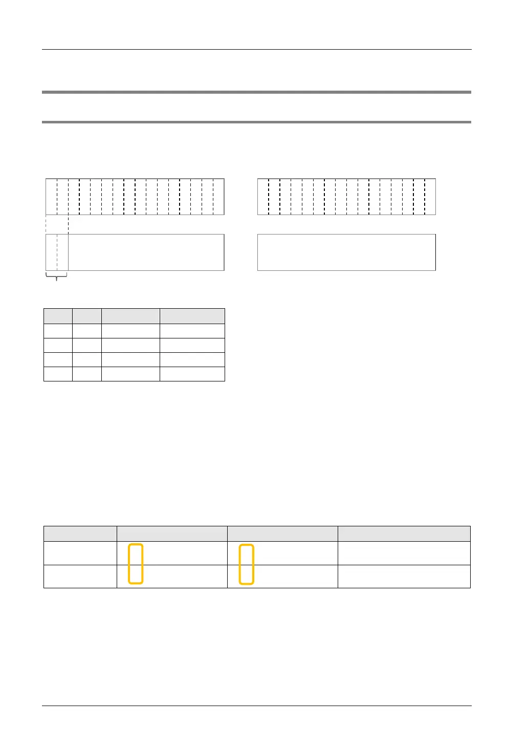
I/O allocation (External input WX)
X
3
F
X
3
E
X
3
D
X
3
C
X
3
B
X
3
A
X
3
9
X
3
8
X
3
7
X
3
6
X
3
5
X
3
4
X
3
3
X
3
2
X
3
1
X
3
0
X
2
F
X
2
E
X
2
D
X
2
C
X
2
B
X
2
A
X
2
9
X
2
8
X
2
7
X
2
6
X
2
5
X
2
4
X
2
3
X
2
2
X
2
1
X
2
0
A
1
A
0
Conversion data of
CH1/CH3/CH5/CH7
(14 bit with sign)
Conversion data of
CH0/CH2/CH4/CH6
(16 bit with sign)
Conversion data switch flag
0 0 CH1 data CH0 data
0 1 CH3 data CH2 data
1 0 CH5 data CH4 data
1 1 CH7 data CH6 data
Role of conversion data switching flag
• The analog input unit reads the analog input data of a maximum of 8 channels using two
memory areas (WX2 and WX3). The most significant two bits are allocated as a conversion
data switching flag for distinguishing channels.
• Conversion data of even numbered channels can be read as 16-bit data as they are.
• As conversion data of odd numbered channels contain the conversion data switching flag of
most significant two bits, mask processing needs to be applied to the data with a user
program. Plus conversion data should be masked by "00", and minus conversion data
should be masked by "11". Create a program in reference to the following programs.
(Example):For reading data of CH3
1 0100 0000 0000 0001 0000 0000 0000 0001
Most significant two bits are
masked by "00".
-1 0111 1111 1111 1111 1111 1111 1111 1111
Most significant two bits are
masked by "11".

 Loading...


