Names and Functions of Parts
2.2 Analog Output Unit (FP0R-DA4)
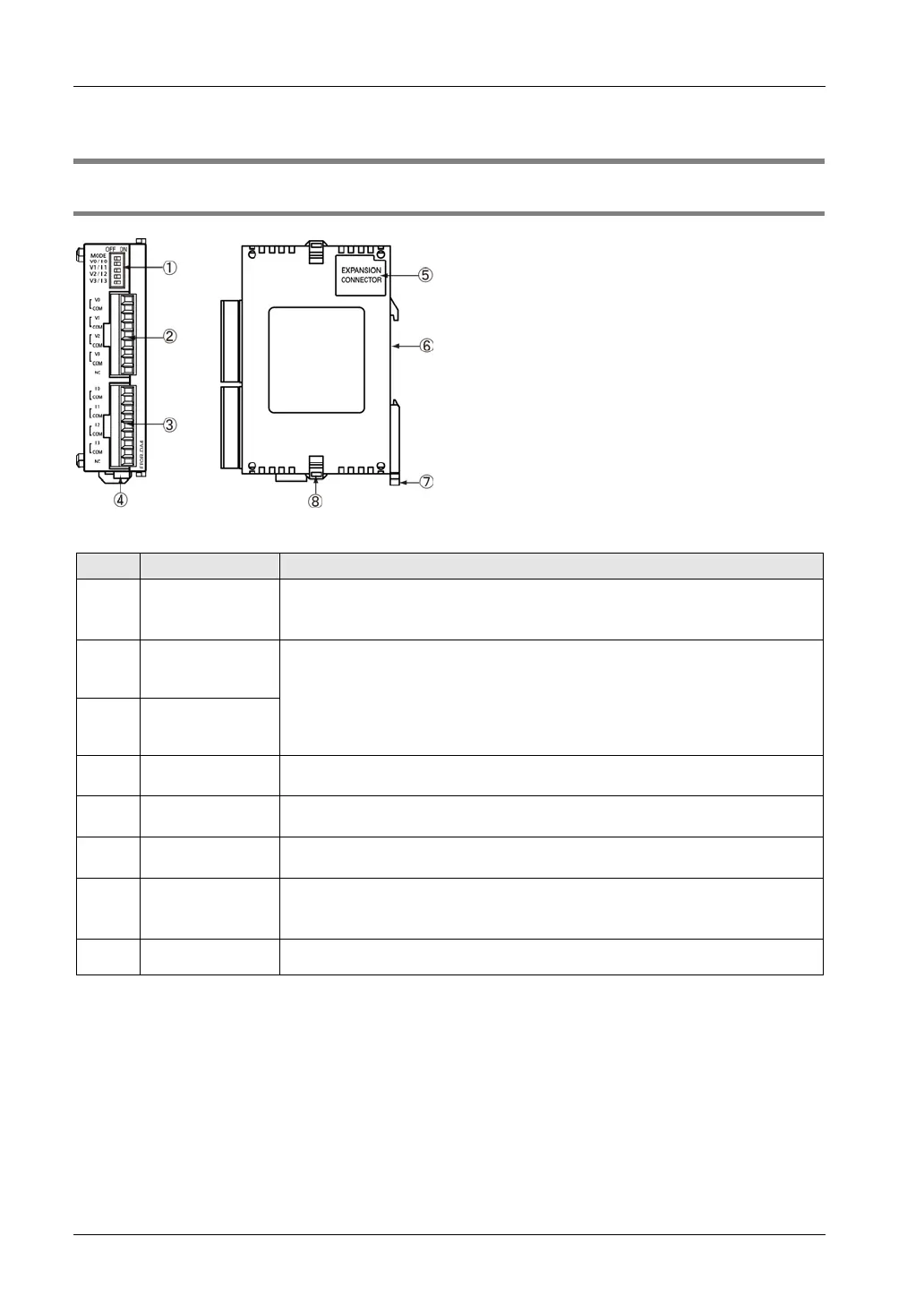
2.2.1 Names and Functions of Parts
Names and Functions of Parts
①
Mode setting
switch
Used for selecting the output range and the output method (voltage/current).
Used for selecting the operation mode (12-bit mode or 14-bit mode compatible
with the conventional product FP0-A04V/A04I).
②
Voltage output
terminal
for CH0-CH3
Used for connecting the analog output device.
The voltage and current vary according to the settings of the mode switch.
They can be selected for each channel.
③
Current output
terminal
for CH0-CH3
④
Power connector
24 V DC is supplied from an external power supply.For connection, use the power
supply cable (AFP0581) that comes with the Unit.
⑤
Expansion
connector
Used for connecting the expansion unit with the internal circuit of the Control Unit.
⑥
groove
It can be installed to a 35-mm-wide DIN rail.
⑦
DIN hook
The unit can be installed to the DIN rail through one-touch operation.
This hook is also used for installing the unit to the Slim Type Mounting Plate
(AFP0803).
⑧
Expansion hook Used for securing expansion units.

 Loading...


